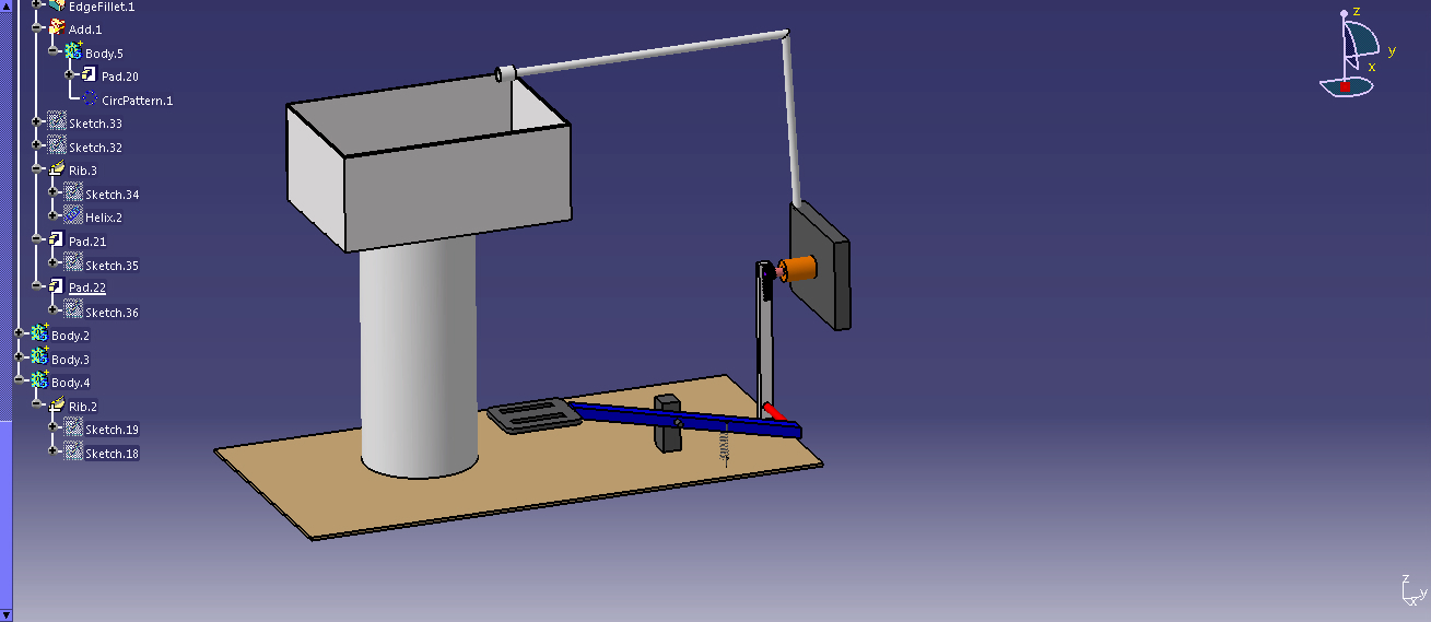
AUTO INDEXING GEAR CUTTING ATTACHMENT FOR PNEUMATIC SHAPING MACHINE
SYNOPSIS
A shaper is used to machine a single job by using a single point cutting tool and hence it can not be used for high production rates. This project intends to use pneumatic shaper for high production of automatic gear cutting with auto indexing work piece. A small ratchet gear structure has been thus devised to demonstrate the gear cutting attachment in shaping machines.
The pneumatic source of power with control accessories is used to drive the ram or the cylinder piston to obtain the forward and return strokes. By this arrangement the forward/reverse stroke of the pneumatic cylinder is adjustable type when compared with the conventional machines. We desired a shaping machine which will automatically index the job and gives automatic tool feed to the pneumatic cylinder.
INTRODUCTION
This is an era of automation where it is broadly defined as replacement of manual effort by mechanical power in all degrees of automation. The operation remains an essential part of the system although with changing demands on physical input as the degree of mechanization is increased.
Degrees of automation are of two types, viz.
- Full automation.
- Semi automation.
In semi automation a combination of manual effort and mechanical power is required whereas in full automation human participation is very negligible.
WORKING PRINCIPLE
- The compressed air from the compressor reaches the solenoid valve. The solenoid valve changes the direction of flow according to the signals from the timing device.

- The compressed air pass through the 5/2 solenoid valve and it is admitted into the front end of the cylinder block. The air pushes the piston for the cutting stroke.
- At the end of the cutting stroke air from the solenoid valve reaches the rear end of the cylinder block. The pressure remains the same but the area is less due to the presence of piston rod. This exerts greater pressure on the piston, pushing it at a faster rate thus enabling faster return stroke.
- The compressed air pass through the 3/2 solenoid valve and it is admitted into the front end of the cylinder block. The air pushes the piston for the gear changer. At the end of the cutting stroke air from the solenoid valve reaches the rear end of the cylinder block.
- The pressure remains the same but the area is less due to the presence of piston rod. This exerts greater pressure on the piston, pushing it at a faster rate thus enabling faster return stroke.
- The screw attached is fixed to the clapper box frame gives constant loads which lower the sapper to enable continuous cutting of the work.
- The stroke length of the piston can be changed by making suitable adjustment in the timer.
APPLICATIONS
- Small and Medium scale industries
- It is very useful in machine shop
- Industrial Application
LIMITATIONS
- While working, the compressed air produces noise therefore a silencer may be used.
- High torque can not be obtained
- Load carrying capacity of this unit is not very high
ADVANTAGES
- Auto indexing mechanism is used to reduce the production time
- Quick response is achieved
- Simple in construction
- Cost of the unit is less when compared to other Machines
- No fire hazard problem due to over loading
- Comparatively the operation cost is less
- The speed of forward and reverse stroke is varied
- Continuous operation is possible without stopping


Post Comment
You must be logged in to post a comment.