When the endless belts are not available, then the belts are cut from big rolls and the ends are joined together by fasteners.
The various types of joints are :
- Cemented joint,
- Laced joint, and
- Hinged joint.
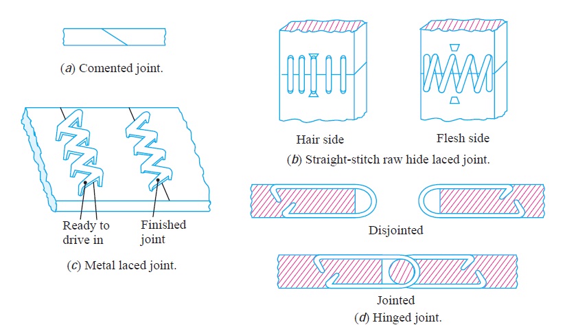
The cemented joint, as shown in Fig. 1 (a), made by the manufacturer to form an endless belt, is preferred than other joints. The laced joint is formed by punching holes in line across the belt, leaving a margin between the edge and the holes. A raw hide strip is used for lacing the two ends together to form a joint. This type of joint is known as straight-stitch raw hide laced joint, as shown in Fig. 1 (b).
Metal laced joint as shown in Fig. 1 (c), is made like a staple connection. The points are driven through the flesh side of the belt and clinched on the inside. Sometimes, metal hinges may be fastened to the belt ends and connected by a steel or fibre pin as shown in Fig. 1 (d).

Kinematic pair
A kinematic pair is a connection between two bodies that imposes constraints on their relative movement. Franz Reuleaux introduced the kinematic pair as a new approach to the study of machines that provided an advance over the motion of elements consisting of simple machines.
Kinematics is the branch of classical mechanics which describes the motion of points, bodies (objects) and systems of bodies (groups of objects) without consideration of the causes of motion. Kinematics as a field of study is often referred to as the “geometry of motion”. For further detail, see Analytical dynamics.
Harten berg & Denavit presents the definition of a kinematic pair:
In the matter of connections between rigid bodies, Reuleaux recognized two kinds; he called them higher and lower pairs (of elements). With higher pairs, the two elements are in contact at a point or along a line, as in a ball bearing or disk cam and follower; the relative motions of coincident points are dissimilar. Lower pairs are those for which area contact may be visualized, as in pin connections, cross heads, ball-and socket joints and some others; the relative motion of coincident points of the elements, and hence of their links, are similar, and an exchange of elements from one link to the other does not alter the relative motion of the parts as it would with higher pairs.
Reference A Textbook of Machine Design by R.S.Khurmi and J.K.Gupta and Wikipedia


Post Comment
You must be logged in to post a comment.