Cast Iron Pulleys
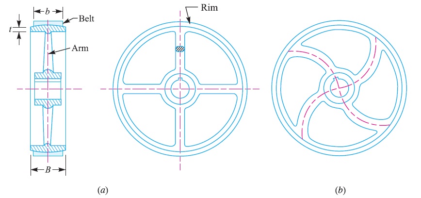
The pulleys are generally made of cast iron, because of their low cost. The rim is held in place by web from the central boss or by arms or spokes. The arms may be straight or curved as shown in Fig. 1 (a) and (b) and the cross-section is usually elliptical.

When a cast pulley contracts in the mould, the arms are in a state of stress and very liable to break. The curved arms tend to yield rather than to break. The arms are near the hub. The cast iron pulleys are generally made with rounded rims. This slight convexity is known as crowning. The crowning tends to keep the belt in centre on a pulley rim while in motion. The crowning may be 9 mm for 300 mm width of pulley face.
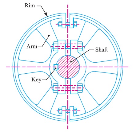
The cast iron pulleys may be solid as shown in Fig. 1 or split type as shown in Fig. 2. When it is necessary to mount a pulley on a shaft which already carrying pulleys etc. or have its ends swelled, it is easier to use a split-pulley.
There is a clearance between the faces and the two halves are readily tightened upon the shafts by the bolts as shown in Fig. 2. A sunk key is used for heavy drives.

Design of Cast Iron Pulleys
The following procedure may be adopted for the design of cast iron pulleys.
1. Dimensions of pulley
(i) The diameter of the pulley (D) may be obtained either from velocity ratio consideration or centrifugal stress consideration. We know that the centrifugal stress induced in the rim of the pulley,
σt = ρ.ν^2
where, ρ = Density of the rim material
= 7200 kg/m^3 for cast iron
ν = Velocity of the rim = πDN / 60, D being the diameter of pulley and N is speed of the pulley.
The following are the diameter of pulleys in mm for flat and V-belts.
20, 22, 25, 28, 32, 36, 40, 45, 50, 56, 63, 71, 80, 90, 100, 112, 125, 140, 160, 180, 200, 224, 250, 280, 315, 355, 400, 450, 500, 560, 630, 710, 800, 900, 1000, 1120, 1250, 1400, 1600, 1800, 2000, 2240, 2500, 2800, 3150, 3550, 4000, 5000, 5400.
The first six sizes (20 to 36 mm) are used for V-belts only.
(ii) If the width of the belt is known, then width of the pulley or face of the pulley (B) is taken 25% greater than the width of belt.
∴ B = 1.25 b ; where b = Width of belt.
According to Indian Standards, IS : 2122 (Part I) – 1973 (Reaffirmed 1990), the width of pulley is fixed as given in the following table :

The following are the width of flat cast iron and mild steel pulleys in mm :
16, 20, 25, 32, 40, 50, 63, 71, 80, 90, 100, 112, 125, 140, 160, 180, 200, 224, 250, 315, 355, 400, 450, 560, 630.
(iii) The thickness of the pulley rim (t) varies from D/300+ 2 mm to D/200+ 3 mm for single belt and D/200+ 6 mm for double belt. The diameter of the pulley (D) is in mm.
2. Dimensions of arms
(i) The number of arms may be taken as 4 for pulley diameter from 200 mm to 600 mm and 6 for diameter from 600 mm to 1500 mm.
Note : The pulleys less than 200 mm diameter are made with solid disc instead of arms. The thickness of the solid web is taken equal to the thickness of rim measured at the centre of the pulley face.
(ii) The cross-section of the arms is usually elliptical with major axis (a1) equal to twice the minor axis (b1). The cross-section of the arm is obtained by considering the arm as cantilever i.e. fixed at the hub end and carrying a concentrated load at the rim end. The length of the cantilever is taken equal to the radius of the pulley. It is further assumed that at any given time, the power is transmitted from the hub to the rim or vice versa, through only half the total number of arms.
Let T = Torque transmitted,
R = Radius of pulley, and
n = Number of arms,
∴ Tangential load per arm,
Wt = T/ {R × (n/2)} = 2 T / R×n
Maximum bending moment on the arm at the hub end,
M = (2T × R)/(R×n) = 2T/n
and section modulus,
Z = π/32 × b1 (a1)^2
Now using the relation,
σb or σt = M/ Z, the cross-section of the arms is obtained.
(iii) The arms are tapered from hub to rim. The taper is usually 1/48 to 1/32.
(iv) When the width of the pulley exceeds the diameter of the pulley, then two rows of arms are provided, as shown in Fig. 19.4. This is done to avoid heavy arms in one row.
3. Dimensions of hub
(i) The diameter of the hub ( d1 ) in terms of shaft diameter ( d ) may be fixed by the following relation :
d1 = 1.5 d + 25 mm
The diameter of the hub should not be greater than 2 d.
(ii) The length of the hub,
L = π/2 × d
The minimum length of the hub is 2/3 B but it should not be more than width of the pulley (B).
Reference A Textbook of Machine Design by R.S.Khurmi and J.K.Gupta


Post Comment
You must be logged in to post a comment.