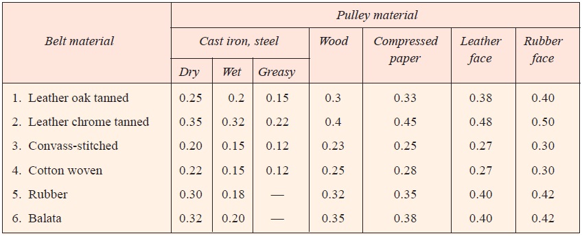
The coefficient of friction between the belt and the pulley depends upon the following factors:
- The material of belt;
- The material of pulley;
- The slip of belt; and
- The speed of belt.
According to C.G. Barth, the coefficient of friction (μ) for oak tanned leather belts on cast iron pulley, at the point of slipping, is given by the following relation, i.e.
μ = 0.54 – {42.6/(152.6 + v)}
where, v = Speed of the belt in meters per minute.
The following table shows the values of coefficient of friction for various materials of belt and pulley.

There are certain factors that help determine the value of the friction coefficient. These determining factors are:
- Belting material used – The age of the material also plays a part, where worn out and older material may become more rough or smoother, changing the sliding friction.
- Construction of the drive-pulley system – This involves strength and stability of the material used, like the pulley, and how greatly it will oppose the motion of the belt or rope.
- Conditions under which the belt and pulleys are operating – The friction between the belt and pulley may decrease substantially if the belt happens to be muddy or wet, as it may act as a lubricant between the surfaces. This also applies to extremely dry or warm conditions which will evaporate any water naturally found in the belt, nominally making friction greater.
- Overall design of the setup – The setup involves the initial conditions of the construction, such as the angle which the belt is wrapped around and geometry of the belt and pulley system.
Standard Belt Thicknesses and Widths
The standard flat belt thicknesses are 5, 6.5, 8, 10 and 12 mm.
The preferred values of thicknesses are as follows:
- 5 mm for nominal belt widths of 35 to 63 mm,
- 6.5 mm for nominal belt widths of 50 to 140 mm,
- 8 mm for nominal belt widths of 90 to 224 mm,
- 10 mm for nominal belt widths of 125 to 400 mm, and
- 12 mm for nominal belt widths of 250 to 600 mm.
The standard values of nominal belt widths are in R10 series, starting from 25 mm upto 63 mm and in R 20 series starting from 71 mm up to 600 mm. Thus, the standard widths will be 25, 32, 40, 50, 63, 71, 80, 90, 100, 112, 125, 140, 160, 180, 200, 224, 250, 280, 315, 355, 400, 450, 500, 560 and 600 mm.
Reference A Textbook of Machine Design by R.S.Khurmi and J.K.Gupta


Post Comment
You must be logged in to post a comment.