Column and Knee Type Milling Machine
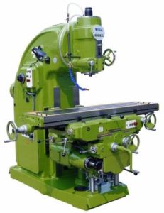
Fig. shows a simple column and knee type milling machine. It is the most commonly used milling machine used for general shop work. In this type of milling machine the table is mounted on the knee casting which in turn is mounted on the vertical slides of the main column. The knee is vertically adjustable on the column so that the table can be moved up and down to accommodate work of various heights. The column and knee type milling machines are classified on the basis of various methods of supplying power to the table, different movements of the table and different axis of rotation of the main spindle. Column and knee type milling machine comprises of the following important parts
1. Base
2. Column
3. Saddle
4. Table
5. Elevating screw
6. Knee
7. Knee elevating handle
8. Cross feed handle
9. Front brace
10. Arbor support
11. Arbor
12. Overhanging arm
13. Cutter
14. Cone pulley
15. Telescopic feed shaft.
The principal parts of a column and knee type milling machine are described as under.
Base
It is a foundation member for all the other parts, which rest upon it. It carries the column at its one end. In some machines, the base is hollow and serves as a reservoir for cutting fluid.
Column
The column is the main supporting member mounted vertically on the base. It is box shaped, heavily ribbed inside and houses all the driving mechanism for the spindle and table feed. The front vertical face of the column is accurately machined and is provided with dovetail guideway for supporting the knee.
Knee
The knee is a rigid grey iron casting which slides up and down on the vertical ways of the column face. An elevating screw mounted on the base is used to adjust the height of the knee and it also supports the knee. The knee houses the feed mechanism of the table, and different controls to operate it.
Saddle
The saddle is placed on the top of the knee and it slides on guideways set exactly at 90° to the column face. The top of the saddle provides guide-ways for the table.
Table
The table rests on ways on the saddle and travels longitudinally. A lead screw under the table engages a nut on the saddle to move the table horizontally by hand or power. In universal machines, the table may also be swiveled horizontally. For this purpose the table is mounted on a circular base. The top of the table is accurately finished and T -slots are provided for clamping the work and other fixtures on it.
Overhanging arm
It is mounted on the top of the column, which extends beyond the column face and serves as a bearing support for the other end of the arbor.
Front brace
It is an extra support, which is fitted between the knee and the over-arm to ensure further rigidity to the arbor and the knee.
Spindle
It is situated in the upper part of the column and receives power from the motor through belts, gears. and clutches and transmit it to the arbor.
Arbor
It is like an extension of the machine spindle on which milling cutters are securely mounted and rotated. The arbors are made with taper shanks for proper alignment with the machine spindles having taper holes at their nose. The draw bolt is used for managing for locking the arbor with the spindle and the whole assembly. The arbor assembly consists of the following components.
1. Arbor
2. Spindle
3. Spacing collars
4. Bearing bush
5. Cutter
6. Draw bolt
7. Lock nut
8. Key block
9. Set screw
Source Introduction of Basic Manufacturing Processes and Workshop Technology by Rajender Singh.


Post Comment
You must be logged in to post a comment.