In the tutorial/lesson we are going to learn about the practical details which are necessary for a layman to use one of the very important device in electronics known as Cathode-Ray Oscilloscope abbreviated as CRO or just Oscilloscope or earlier known as Oscillograph. At the completion of this tutorial we will be able to operate the CRO as per our requirement in different activities or experiments.
What is a CRO and what is it used for? An Oscilloscope is an electronic device generally used to obtain the wave-form of different signals applied to it. Unlike a MultiMeter which is also used for the measurement of the values of different signals or resistances or any other electrical parameter, which depicts the instantaneous values of an electrical parameter, an Oscilloscope on the other hand expands the time window for the observer to have a better picture regarding the properties of the signal applied to it. There are many other merits and applications of CRO which we are going to discuss later in this tutorial. First we must answer another very common or elementary inquiry about CRO’s.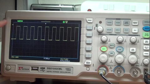
What is the idea behind a CRO? To understand the basic functioning of a CRO lets’ pretend that a device ( may even be a multi-meter) stores various measurement values at different instants of time of a particular signal and then we put all the measured values in a single paper, then what we get is all those measurement being traced over a certain period of time. This is what a CRO basically does, although there is a very complex mechanism behind the acquiring of these values from the signal but we don’t need to go further into that. Unlike an Oscilloscope, a multi-meter provides a slit window or an instantaneous window for observing a signal.
Use and Description of CRO
While performing an operation on CRO one must be very curious about the functions of various button or knobs provided in the Oscilloscope, we will be discussing all the typical functions performed by an Oscilloscope and how these knobs function according to our whims. A typical Oscilloscope basically comprises of three components:-
- The Display: It is a LCD or CRT display which consists of various horizontal and vertical lines in the way of a matrix which covers the whole display. This LCD or CRT screen is responsible for the display of the captured instants of the signal for further observation.
- The matrix included in the screen helps in calculation of the range of the extremes of the signal under observation. The matrix can be of same number of lines in both the axis or not, that depends on the manufacturer. Each box in the matrix has its range depending on the values of voltage-scale and time-base scale knobs which we are going to discuss later in this tutorial.
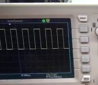
- The horizontal axis in the display represents time scale or time base. The time base is divided in a bunch of boxes, due to the matrix, these segments represents a small window of time which helps in analyzing the signal. This scale can be adjusted according to our needs with one of the knobs provided in the control panel of the CRO. For ex, a segment can be of 500 µs. So if the whole horizontal axis consists of n segments then the full scale reading will be n*500 µs.
- The vertical axis represents voltage scale of the signal and like the time base it is also divided in a series of segments. The variation of these segments can be controlled with the voltage-scale knob. For ex, a division on the vertical axis can be of 1 mV. If the total number of boxes is m in vertical scale then the full scale reading will be m*1 mV.
- The Knobs or buttons: These are provided to have a closer look at the signals and to play around with them. These control the basic functionality like display, time and voltage scale of the Oscilloscope, no of signals to be displayed, positioning of signals and many other things of our interests to make it easier to analyze. Few important but basic adjustments that we have on a Oscilloscope are:-


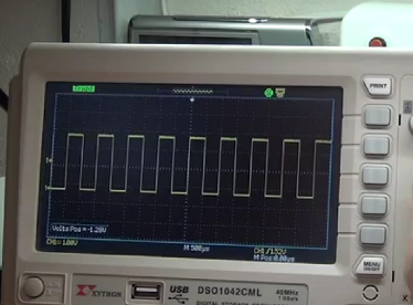
- Vertical position (each channel): This knob is provided for each channel of the Oscilloscope, so if you have an Oscilloscope with more than one channel (generally CRO’s have two channels), you can manually adjust the vertical alignment of each channel in the display according to your wish. This means that without changing the scale of the signal you can move the signals up and down in the display. This also helps when the signal goes out of the range of the display then you can pull the signal down so that it comes under the range of the display. This becomes utterly useful when you have to take reading.
- Horizontal position (all channels): This is one knob for every signal coming into the CRO. It helps in moving the signal horizontally along the time-axis. If you want to study a specific part of the signal or if you want to place the signal at specific positions of the display so that it becomes easier for the purpose of observation, you can surely do that with this help of this knob.
Things are now going to get interesting, 🙂
- Voltage scale (each channel): With the help of this knob you can change the horizontal scale of each segment in the display matrix. That is you can change the volts/division value of the display with the use of this knob. It provides the essence of zoom in/out view of the signal. Moreover, it allows the user to make the signal go into the range of the display of the CRO, so that it could be properly reviewed.
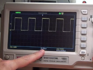
- Time-base (all channels): This knob helps to adjust the total amount of time window you want to view in the display by increasing or decreasing the time per division value of each box in the matrix. You can increase the value by rotating the knob to see a larger time window or you can decrease the value of the knob to see a smaller time window for closer observation of the signal.
- Trigger position: This knob helps in keeping the signal still for better observation of the signal. The signal might not be stand still in most of the cases, adjusting this knob helps in stopping the flickering of the signal. There are different kinds of trigger available depending on the Oscilloscope i.e. leading-edge triggered, lagging-edge triggered etc.
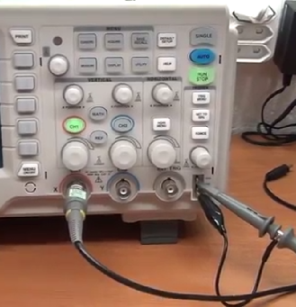
- The Probes: These are the connecting wires or the connection bridge between the signal generating source and the CRO. A probe is a wire which have 2-clipper(one for each of the two terminals of the signal generator, most often one of the clipper of this end is connected to ground) at one end and one round connector at the another end (which goes into the Oscilloscope). Most often there are two probes each one for the two channels available in the CRO. In this figure the other end of the probe is connected to the signal tester available inside the CRO for testing purposes. Here you can see the two clippers at one end of the probe and one round connector at another end of the probe.
In the next tutorial we will be have a further insight abut some other basic operations offered by an Oscilloscope, some other knobs of an Oscilloscope which are commonly used in day-to-day experiments and also we will be doing an experiment to have a crystal clear idea about the practical uses of a CRO.