Design and Analysis of Snap Fit Joints Download Report -Mechanical Projects
ABSTRACT:
Snap fits are the simplest, quickest and most cost effective method of assembling two parts. Basically, a molded undercut on one part engages a mating lip on the other. This method of assembly is uniquely suited to thermoplastic materials due to flexibility, high elongation and ability to be molded into complex shapes. In this research paper a 2D model of snap lock is generated in ANSYS software to study the non linear contact analysis between the mating lips. Result generated by the FEA software ANSYS, allows to evaluate and optimize the snap joint prior to committing costly prototypes and tooling.

Introduction :
Snap-fits are the simplest, quickest and most cost effective method of assembling two parts. When designed properly, parts with snap-fits can be assembled and disassembled numerous times without any adverse effect on the assembly. Snap-fits are also the most environmentally friendly form of assembly because of their ease of disassembly, making components of different materials easy to recycle.
Although snap-fits can be designed with many materials, the ideal material is thermoplastic because of its high flexibility and its ability to be easily and inexpensively molded into complex geometries. Other advantages include its relatively high elongation, low coefficient of friction, and sufficient strength and rigidity to meet the requirements of most applications.
The designer should be aware that the assembly may have some “play“ due to tolerance stack-up of the two mating parts. Some snap-fits can also increase the cost of an injection molding tool due to the need for slides in the mold. An experienced designer can often eliminate the need for slides by adding a slot in the wall directly below the undercut or by placing the snaps on the edge of the part, so they face outward.
Types of Snap-Fits
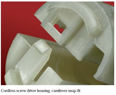
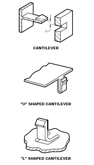
Most engineering material applications with snap-fits use the cantilever design. The cylindrical design can be employed when an unfilled thermoplastic material with higher elongation will be used (a typical application is an aspirin bottle/cap assembly).
Other types of snap-fits, which can be used, are the “U“ or “L“ shaped cantilever snaps (see Part V for more detail).
These are used when the strain of the straight cantilever snap cannot be designed below the allowable strain for the given material.

SNAP FIT DESIGN CONSIDERATION
The snap joint deals with various types of common issues like stress concentration, creep and fatigue. This should be resolved during designing a joint. To resolve these issues there are some guidelines to be followed during design practice. Most of the snap joint are formed by the material commonly used is thermoplastic. We know that due to sharp edges or corners common failure is stress concentration, to avoid this failure we have one solution to incorporate fillet in a desired manner. If sink marks are an issue, a smaller radius can be used, but it may increase the stress in this area. The stiffness of thermal plastic can be improved by adding glass fiber or composite to the base resin. Creep or more accurately stress relaxation, can result in a reduction of the holding force between the two components connected by the snap fit. To avoid creep there should be relaxation in tension and relaxation in bending. To avoid fatigue failure, choose a material which can perform well in fatigue. This material can be chosen by comparing their S/N curves prior to the snap joint application. Reducing these issues is a major challenge by considering all the parameters in their desired form of a snap fit joint.
DEVELOPMENT OF SNAP JOINT IN FINITE ELEMENT MODEL
A two-dimensional finite element model of a tapered snap lock was developed to investigate various factors influencing snap fit pull strength. The model was generated in FEA software ANSYS, which allows nonlinear contact analysis and conduct results for several hundred iterations easily. Provisions were made to adjust the snap catch rake angle, size of snap beam support region and amount of beam taper or taper ratio. Since the deflection behavior of a snap beam is primarily two-dimensional. For efficient results fine meshing is done. Nodes on the outer periphery of this matting region were fixed by edge meshing. Coefficient of friction between the two mating surface was also defined as a material constant elements. A support region around the base of the snap beam was also included in the model to capture the influence of support stiffness. The solutions are progressed by incrementally moving the mating contact surface vertically in the y-direction until total cam-out of the snap beam catch surface occurred. Typical runs on a high end personal computer would required about 200-500 iterations and take about 2-10 minutes.
CONCLUSION
Wide research has been carried out in the field of design of snap fit joint in plastic parts. From these paper it can be noted that the most significant factor influencing the push or pull strength of a cantilever snap fit are snap beam taper ratio , catch rake angles and coefficient of friction between the mating surface. To optimize plastic molded component utilizing robust snap fit, Finite element analysis software like ANSYS plays a vital role. For further study this approach can be expanded to analyze more complex three dimensional snap fits without fabricating the component their prototypes can be made.


Post Comment
You must be logged in to post a comment.