Abstract –
All the automobile vehicles available are always set to changing speed and torque between engine and driving wheels. Torque is not directly changed but it can be done in the form of power using a suitable device. It is a very useful method that we adopt, and it is also easily affordable. Many other alternative, even though more elegant, and appear to be more effective are not feasible when it comes to transmission.
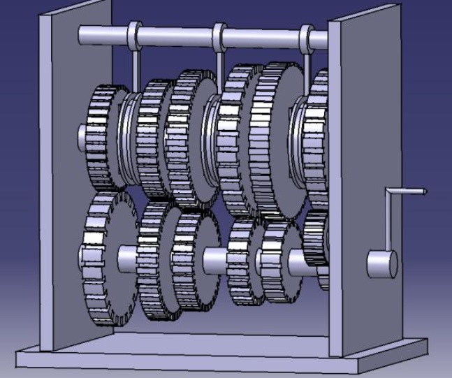
This project mainly focuses on the design and fabrication of a gear box that can transmit torque to the maximum and also helps to do some useful work in automobile where power transmission is a major factor. The transmission of power is done in six speeds in this project. The setup uses two shafts and thirteen gears arranged in suitable distances to achieve the desired torque and speed.
INTRODUCTION
The present day world is moving towards globalization. Now to keep at par with the global market, the countries follow a different set of standards.
The main purpose of these standards is to make a product available, in every nook and corner of the world with exactly the same specifications without any single change.
The standards are being adopted in each and every field of technology and science. These changes, especially in automobile next to the clutch are the transmission in the
transmission system of a motor vehicle. The word ” transmission‟ is used for a device that is located between clutch and propeller shaft. The device used for the transmission is Gear Box.

THE WORKING OF 6 SPEED CONSTANT MESH GEAR BOX:
The six speed constant mesh gear box has two shafts , one for the input and the other for output. Six gears are mounted on both the shafts and are in constant mesh. Ball
bearings are connected to the gears on the output shaft which makes them to rotate freely on the output shaft.
The output gears have extensions on one side for the engagement purpose. The clutches are engaged and disengaged with the gears by the use of levers. The clutches are keyed to the output shaft. The engine flywheel is connected to the input shaft.
The gears on the output shaft rotate freely on the bearings. In order to engage the dog clutch with the gear the respective lever is moved. This moves the clutch towards
the gear and the dog gets engaged with the extensions on the gear. The rotation is transferred to the output shaft. The wheels connected to the output shaft are also rotated.
FABRICATION PROCESS
The material for shaft and gear are taken as C 45 steel. The gears and the shafts are fabricated in the following method.
Gears
Machining, drilling and boring
These operations where done in gears at centre to produce hole in the gears to hold on the shaft.
Shafts
Turning-These operations are done in lathe for the shaft in which the cylindrical objects may be produced. With the work piece rotating and single point cutting tool.
Welding-This sort of operation is done to fix the gears onto the shaft.


Post Comment
You must be logged in to post a comment.