Design and Structural Analysis of Single Plate Friction Clutch
Abstract
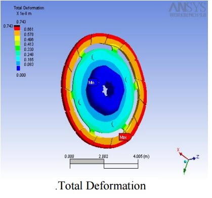
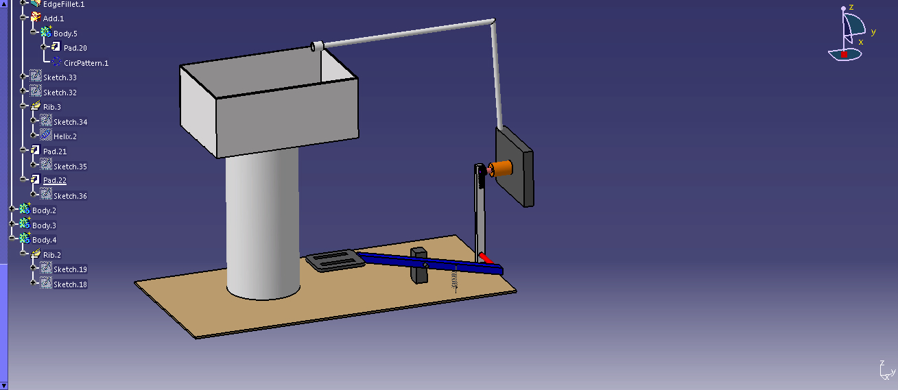
In design of the friction clutches of automobiles, knowledge on the thermo-elasticity a property is very informative in the initial design stage. Especially, the precise prediction technique of maximum structural stress should be requested in design of mechanical clutches for their durability and compactness. In this study, an efficient and reliable analysis technique for the design of the mechanical clutches by using computer modeling and numerical method is developed. This work contains stress analysis of single plate clutch of the automobile, in which the stresses and forces developed in the clutch is tried to reduce with the help of software approach. The detail study of clutch and modeling of clutch is done in pro-e software and the analysis is to be done in Ansys software. Also in this work efficient and reliable design of mechanical clutch is find out.
Introduction
Clutch is a device used in the transmission system of a vehicle to engage and disengage the transmission system from the engine. Thus, the clutch is located between the engine and the transmission system. In a vehicle, the clutch is always in the engaged position. The clutch is disengaged when starting the engine, when shifting gears, when stopping the vehicle and when idling the engine. It is disengaged by operating the clutch pedal i.e. by pressing the pedal towards the floor of the vehicle. The clutch is engaged when the vehicle has to move and is kept in the engaged position when the vehicle is moving. The clutch also permits the gradual taking up of the load, when properly operated; it prevents jerky motion of the vehicle and thus avoids putting undue strain on the remaining parts of the power transmission .
Single plate friction clutch
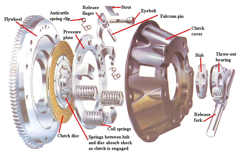
The parts of a single plate clutch can be seen below .It has only one clutch plate, mounted on the splines of the clutch shaft. This is the most commonly used type. The flywheel is mounted on the crankshaft, and rotates with it. The pressure plate is fixed on the flywheel through the pressure plate is fixed on the flywheel through the clutch springs. The plate rotates freely on the clutch shaft. It can also be moved axially along the clutch shaft. The axial movement of the pressure plate is effected by pressing the clutch pedal. The end of the clutch shaft rests and rotates freely in the pilot bearing housed at the centre of the flywheel.

Clutch Plates in Automobiles and Motorcycles
Clutch plate in a car is controlled by the left-most pedal. This makes use of hydraulics or a cable connection. The clutch may be physically located in close proximity to the pedal, but remote means of actuation are required to remove the effect of slight engine movement. If there is no pressure on the pedal, it means that the clutch plates are engaged. It gets disengaged once the clutch pedal is depressed. Cars can also function with manual transmission. In this there are cogs that have matching teeth to synchronize the speed. One can select gears with the help of these cogs. In motorcycles, the clutch is operated by the clutch lever. One can engage the clutch plate by applying no pressure on the lever. Pulling the lever back towards the rider disengages the clutch plates. Slipper clutch plates are often used by racing motorcycles to get rid of engine braking.
Structural Analysis
Structural analysis comprises the set of physical laws and mathematics required to study and predicts the behavior of structures. The subjects of structural analysis are engineering artifacts whose integrity is judged largely based upon their ability to withstand loads; they commonly include buildings, bridges, aircraft, and ships. Structural analysis incorporates the fields of mechanics and dynamics as well as the many failure theories. From a theoretical perspective the primary goal of structural analysis is the computation of deformations, internal forces, and stresses. In practice, structural analysis can be viewed more abstractly as a method to drive the engineering design process or prove the soundness of a design without a dependence on directly testing it.

It consists of linear and non-linear models. Linear models use simple parameters and assume that the material is not plastically deformed. Non-linear models consist of stressing the material past its elastic capabilities. The stresses in the material then vary with the amount of deformation.
It includes the following methods,
1) Analytical Methods
2) Strength of materials methods (classical methods)
3) Finite element methods (FEM)


Post Comment
You must be logged in to post a comment.