8051
EC
Electronics Tutorials
EngTech
MI Lab
Micocontroller
abb blown fuse indicator, ac fuse blown indicator, advantages of blown fuse indicator, apartment multi channel fuse blown indicator & annunciation, application of blown fuse indicator, blown ac fuse indicator circuit, blown fuse indicator abstract, blown fuse indicator advantages, blown fuse indicator application, blown fuse indicator circuit diagram, blown fuse indicator efy, blown fuse indicator for ac load, blown fuse indicator introduction, blown fuse indicator led circuit, blown fuse indicator led display, blown fuse indicator light, blown fuse indicator mini project, blown fuse indicator pdf, blown fuse indicator ppt, blown fuse indicator project pdf, blown fuse indicator project report, blown fuse indicator project report pdf, blown fuse indicator schematic, blown fuse indicator switch, blown fuse indicator terminal block, blown fuse indicator wikipedia, blown fuse indicator with alarm, blown fuse indicator with alarm pdf, blown fuse indicator working, bussmann blown fuse indicator, construction of blown fuse indicator, dc fuse blown indicator, disadvantage of blown fuse indicator, ferraz blown fuse indicator, ferraz shawmut blown fuse indicator, fuse block blown fuse indicator, fuse blown indicator circuit, fuse blown indicator for substations, fuse blown indicator in inverter, fuse blown indicator in microtek inverter, fuse blown indicator led, fuse blown indicator project, fuse holder blown fuse indicator, high voltage fuse blown indicator with display on computer pc, high voltage fuse blown indicator with voice, high voltage fuse blown indicator with voice alert, high voltage fuse blown indicator with voice alert circuit diagram, high voltage fuse blown indicator with voice alert ppt, high voltage fuse blown indicator with voice based announcement system, how does a blown fuse indicator work, how does blown fuse indicator work, how to make a blown fuse indicator, introduction of blown fuse indicator, led blown ac fuse indicator circuit diagram, mersen blown fuse indicator, neon blown fuse indicator, optically isolated fuse blown indicator, phoenix blown fuse indicator, ppt on blown fuse indicator, project on substation fuse blown indicator, remote blown fuse indicator, simple blown fuse indicator, substation fuse blown indicator, substation fuse blown indicator pdf, substation fuse blown indicator project, substation fuse blown indicator wikipedia, what is blown fuse indicator, working of blown fuse indicator
Amisha
0 Comments
HIGH VOLTAGE FUSE BLOWN INDICATOR WITH DISPLAY ON PC
AIM:
The purpose of this project is to alert the remote user incase of a fuse in a critical electrical equipment got fused.
INTRODUCTION:
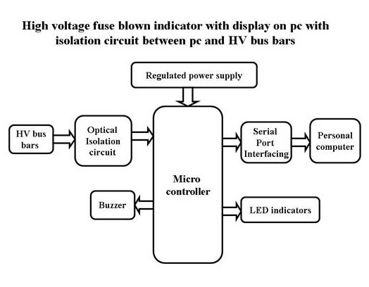
This consists of two electrically isolated power sensors for sensing the presence of electrical power. One of the power sensors is connected before the fuse to be monitored and the other after the fuse. The power status from these sensors is fed to a microcontroller. Microcontroller continuously monitors the status of these two sensors. If the power status of second sensor is low and the first sensor is high, then the microcontroller identifies this as a break in fuse circuit and sends an appropriate message to a Computer connected to it. If both the sensors output goes low then microcontroller identifies this as power supply failure and sends the appropriate message to the Computer.
Once the data is available with computer, we can use this data to send e-mail to the concern personal about the fault. The storage of power status information in computer also helps in viewing historical data.
The objectives of the project include:
- Real-time fuse monitoring.
- Alarming in fuse blown situations.
- Sending the status of the fuse to PC.
The project provides us exposure on:
- Embedded C program.
- PCB designing.
- Electrical isolation between two devices.
- Serial communication between the controller and PC.
- Implementation of RS232 protocol.
The major building blocks of this project are:
- Microcontroller based control system with regulated power supply.
- Two electrically isolated power status sensors.
- Microcontroller to PC interfacing circuit.
- Serial data cable for PC connectivity.
Block Diagram:
Post Comment
You must be logged in to post a comment.