Introduction
Today you have the FPGA on 18 counts as one of the up and down using sequential LED will design a binary counter. So let’s start.
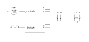
First, our design will consist of what it as hardware. The increase itself at the end of a certain period in our design we want to counter or reduce the need to have a signal input to the FPGA so that when the signal comes to our counter you change occurred. We will use 50 MHz crystal found on board t to perform this operation (50 MHz signal 20 nano brings about change in seconds, we need to put a hold on the program so we can see the change.) Crystal will perform our every rising edge triggering process.
Our counter counting down and we need to specify the direction of the counter with an external input because we want to count up from the outside, we can use any switch or button on the board for it.
What we were talking about so far counter to the input parameters. The output of the counter 18-bit vector (17 downto 0) we define by identifying our departure. This output is low and the high-end pin assignment should be made considering.
We have designed our system diagram as shown in this diagram below illustrates the Entity us part of our program.
 After designing of the entity we can move our program.
Library ieee; -iee And processing standards library
user ieee.std_logic_1164.all,
user ieee.numeric_std.all,
library altered;
user altera.altera_syn_attributes.all;
Entity door is
port
(CLOCK_50: in std_logic; whose input clock signal KEY: in std_logic; -one belirkeyic button LED: out std_logic_vector (17 downto 0) -18-bit output vector is
);
end doors;
architecture ppl_typ of the door is
signal Prescali are: integer range 0 to 800000: = 0; -Signal Identification
signal result: integer range 0 to 131 071 = 0;
begin
LED <= is std_logic_vector (to_unsigned (result, 18)); We assign a variable output signal several times.
PROCESS (CLOCK_50)
BEGIN
if (CLOCK_50’EVENT AND CLOCK_50 = ‘1’) THEN -Increased edges defining line
if (Prescali on <800000) THAN – Prescali We make saydırarak standby signal to the program.
Prescali and <= Prescali and + 1;
ELSE
Prescali for <= 0;
END IF;
if (Prescali = 0) THAN
case KEY is -Case structure here was determined counting direction by controlling the key button
when ‘1’ => – key 1 What is to be done
if (result <131 071) THEN this will count to the max 131 071 e -18-bit counters until it reaches the value for money was increased
result <= result + 1;
ELSE
result <= 0;
END IF;
when ‘0’ => -Key 0 is to be performed transactions
if (result> 0) THEN
result <= result-1;
ELSE
result < = 131 071;
END IF;
end case;
END IF;
END IF;
END PROCESS; -Process In the end
end;
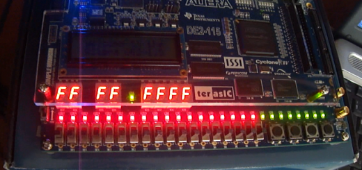
Clock_50 used in the program, and led key variables used or boarden fpga design by making the appropriate pin assignments can be implemented.


Post Comment
You must be logged in to post a comment.