Geneva Wheel Mechanism
Introduction
The Geneva wheel, or Maltese cross, is a cam like mechanism that provides intermittent rotary motion & is widely used in both low and high-speed machinery. Although originally developed as a stop to prevent over winding of watches, it is now extensively used in automatic machinery, e.g. where a spindle, turret, or worktable must be indexed. It is also used in motion picture projectors to provide the intermittent advance of the film.

-
Geneva Wheel Design
The basic design criteria of a Geneva wheel is that the center-lines of the slot and crank are mutually perpendicular at engagement and at disengagement. The crank, which usually rotates at a uniform angular velocity, carries a roller to engage with the slots. During one revolution of the crank the Geneva wheel rotates a fractional part of the revolution, the amount of which is dependent upon the number of slots. The circular segment attached to the crank effectively locks the wheel against rotation when the roller is not in engagement and also positions the wheel for correct engagement of the roller with the next slot.
The design of the Geneva mechanism is initiated by specifying the crank radius, the roller diameter and the number of slots. At least 3 slots are necessary but most problems can be solved with wheels having from 4 to 12 slots. The angle (β) is half the angle subtended by adjacent slots i.e.
B=360/ 2N
Where n is the number of slots in the wheel.
Then, defining r2 as the crank radius we have,
c= r2/sinB
Where c is the center distance. Note that the actual Geneva wheel radius is more than that which would be obtained by a zero-diameter roller. This is due to the difference between the sin and the tangent of the angle subtended by the roller, measured from the wheel center. The final step in the design process is to choose a convenient radius for the circular pert of the Geneva wheel, which meshes with the input wheel locking the Geneva wheel.
- Project Design Specification
The Geneva Wheel Mechanism designed in this project has the following design specifications:
-Number of Slots = 5
– Radius of Crank = 50 mm
– Distance between centers of Geneva Wheel and Crank = 85.1 mm
– Outer radius of Geneva Wheel = 61.81 mm
– Radius of circular locking part = 42.7 mm
– Slot width = 10 mm
– Length of Slot = 27 mm
– Shaft diameter = 16 mm
- The Manufacturing Processes
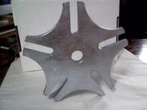
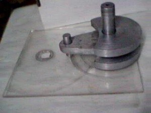
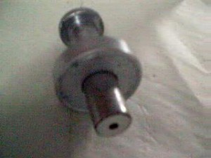
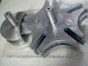
The Geneva Wheel Mechanism, which was manufactured, had 9 parts. They were the two Geneva wheel pieces, two circular locking
wheels, a Crank Pin, a spacer plate, two Shaft Pins to carry the Geneva wheel and the input shaft and a Base plate. The Geneva wheel was manufactured by turning a 10 mm thick MS Plate to the external dimensions. Then the profile was punch marked on the plate. The plate was put in a indexing milling machine and the profile was milled to the required dimensions including the cutting of
slots.
The locking wheel was also punch marked and milled to the required dimensions. The crank pin was made by gas cutting the required shape and the roller pin was fitted at the required distance of 50 mm from the crank center. All the other components were turned to
the required dimensions.
The Base plate was cut out of a 4 mm thick transparent acrylic plate. The holes for carrying the shafts were then drilled by using a 16 mm drill taking care of the distance between the centers.
- Geneva Wheel Analysis
The Analysis of Geneva wheel is done by drawing the position of the pin and the Geneva wheel at the required position.
The position of the Geneva wheel is given by,
Differentiating this with respect to time we get,

Differentiating again with respect time we get,

These equations are valid only in the region –(90-b) to (90-b) of the input crank angle. At all other angles the Geneva wheel is stationary and hence both angular velocity and acceleration are zero. Both the angular and acceleration are plotted as a function of input angle in the accompanying plot for an input angular velocity of 1 rad/sec.
- Conclusion
There is a sudden acceleration when the Geneva wheel stars rotating. Several methods have been employed to reduce the wheel acceleration in order to reduce inertia forces & the consequent wear on the sides of the slot. Among these is the idea of using a curved slot. This does reduce the acceleration, but it increases the deceleration and consequently the wear on the other side of the slot.
The Inverse Geneva mechanism, which is a variation of the Geneva mechanism, is used where the wheel has to rotate in the same
direction as crank. It requires less radial space and the locking device can be a circular segment attached to the crank that locks by wiping against a built up rim on the periphery of the wheel.




Post Comment
You must be logged in to post a comment.