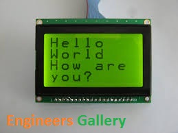
The 16×2 Character LCDs have their own limitations; they can only display characters of certain dimensions. The Graphical LCDs are thus used to display customized characters and images. The Graphical LCDs find use in many applications; they are used in video games, mobile phones, lifts etc. as display units. Various graphical LCDs are available in the market with different sizes. Here JHD12864E Graphical LCD has been explained. This LCD has a display format of 128×64 dots and has yellow-green colour backlight. Each LCD needs a controller to execute its internal operations. This LCD uses two KS0108 controllers.
The 128×64 LCD is divided into two equal halves with each half being controlled by a separate KS0108 controller. Such LCDs (using KS0108 controller) involve paging scheme, i.e., whole LCD is divided equally into pages. The paging scheme of the graphical LCD can be easily understood from the following table.
- 128×64 LCD implies 128 columns and 64 rows. In total there are (128×64 = 1024) pixels.
- 128×64 LCD is divided equally into two halves. Each half is controlled by a separate controller and consists of 8 pages. In above diagram, CS stands for Controller Select.
- Each page consists of 8 rows and 64 columns. So two horizontal pages make 128 (64×2) columns and 8 vertical pages make 64 rows (8×8).
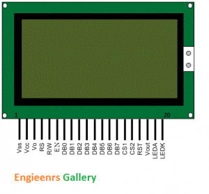
Pin Description:
| Pin no. | Function | Name |
| 1 | Ground (0 V) | Vss |
| 2 | Supply voltage; 5V | Vcc |
| 3 | Contrast adjustment | Vo |
| 4 | High to display data; Low for instruction code | Register select (RS) |
| 5 | Low to write to the register; High to read from the register | Read/Write (R/W) |
| 6 | Reads data when high; Writes data at high to low transition (falling edge) | Enable (EN) |
| 7 |
8-bit data pins |
DB0 |
| 8 | DB1 | |
| 9 | DB2 | |
| 10 | DB3 | |
| 11 | DB4 | |
| 12 | DB5 | |
| 13 | DB6 | |
| 14 | DB7 | |
| 15 | Chip selection for IC1; Active high | CS1 |
| 16 | Chip selection for IC2; Active high | CS2 |
| 17 | Reset signal; Active low | RST |
| 18 | Output voltage for LCD driving | Vout |
| 19 | Backlight VCC (5V) | LED A |
| 20 | Backlight Ground (0V) | LED K |


Post Comment
You must be logged in to post a comment.