How to Interface 4×4 Matrix Keypad with LPC2148
[nextpage title=”Summary” ]Switch is the most widely used input device. When a switch is pressed either low or high signal is given to controller depending upon the circuit designing. This approach requires one pin for a single switch. With increasing requirement of input devices, more numbers of controller pins are required which may not be available all the time. For example, to enter value from 0 to 15, we need 16 pins of controller to be interfaced with switches. To reduce number of required pins, we can arrange keys in matrix form.
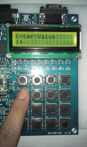
Matrix keypad is one of the widely used input devices. Some of the application includes Mobile keypad, Telephone dial pad, calculator, ATM etc. Keypad provides an easy way to allow user to provide input to any system. In this article, we will explain how to interface 4×4 matrix keypad with LPC2148. The pressed key will be displayed on LCD.
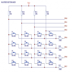
[/nextpage][nextpage title=”Description” ]In matrix keypad, keys are connected in rows and columns. When any switch is pressed, rows and columns come into contact which is detected by controller to identify which key has been pressed. Let’s see how keypad works.
Keypad in general looks like this.

For identify the pressed key, we have to follow given procedure.

Step-1: Set output port to logic 0 and input port to logic 1.
If all rows are set to logic 1 and no key is pressed, reading input port will result all input pins set at logic 1 as there is no path available for current to flow between Vcc and Ground. It is a function of micro-controller to read input port continuously to identify whether the key has been pressed or not.
Step-2: Whenever any key is pressed, one of the input pin will be grounded by pressed key. By reading input pins, we can identify the column in which key has been pressed by following table.

So now we have identify that in which column the key has been pressed by user. Now we have to identify the row in which key has been pressed.
Step-3: Ground first row and set rest of the rows. Read input port. If all are 1s, no switch in that row is pressed. Now ground second row and set all others rows at logic 1 and see whether any key has been pressed in that row or not. Continue same process until you find out in which row, key is pressed.
Once we know column and row in which key has been pressed, we can identify the pressed key easily.
Step-4: Ground all rows and read columns. If any of the columns has 0, keep doing this process unless all columns are 1.
Step-5: Once we have identified the pressed key, we can display it on LCD, Serial Port etc. as per the requirement.
[/nextpage][nextpage title=”Circuit Diagram” ]
[/nextpage]


Post Comment
You must be logged in to post a comment.