Abstract
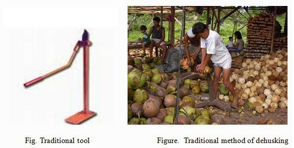
Generally, coconuts are dehusked manually using either a machete or a spike. These methods require skilled labour and are tiring to use. Attempts made so far in the development of dehusking tools have been only partially successful and not effective in replacing manual methods. The reasons quoted for the failure of these tools include unsatisfactory and incomplete dehusking, breakage of the coconut shell while dehusking, spoilage of useful coir, greater effort needed than manual methods, etc.
The present work involved the design, development and testing of a coconut dehusker which overcomes the drawbacks of the previously reported implements. The design and developmental stages called for a closer look at the magnitude and direction of the dehusking forces and their generation mechanisms. Details of a simple, sturdy and efficient hydraulic dehusker unit, financially beneficial to labourers and producers, are given here. Comparative assessment of this unit in relation to those reported in the literature is provided. Test results and assessment of the present unit in both laboratory and field conditions are also reported. Safety aspects are incorporated. The unit can dehusk about 70 coconuts per hour compared with about 40 nuts per hour from a skilled worker using the spike method. It can be operated by unskilled labourers. Cost benefit analysis indicates that it should be commercially viable.

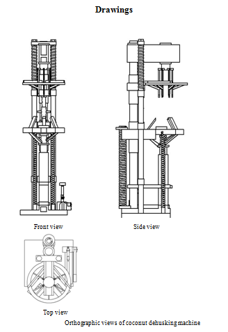
Machine description
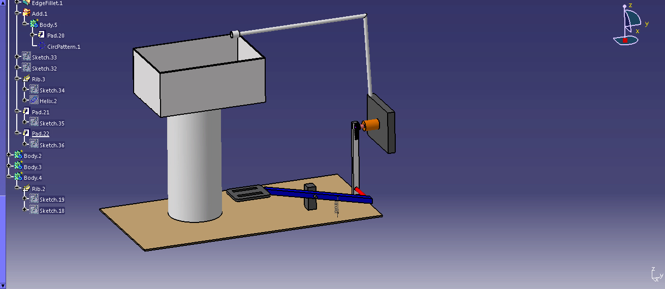
This coconut dehusking machine peels off the coconut husk from coconut fruit to obtain dehusked coconut fruit via mechanical controlled dehusking devices. The coconut is placed on the holder in vertical position. The holder is moved up by the foot operation mechanism. The top assembly which comprises the gripper pokers held vertically with link mechanism and is pivoted to the coconut body. The top assembly movement effects the pokers to move in the downward slide to poke into the coconut and at certain depth will make the pokers to move apart at 45 degree by the pusher link mechanism to tear apart the husk with force. The foot operated holder can be adjusted to the required height by the height adjuster. The foot lever is operated to continue the pumping till the mechanism is pulled down to its lowest position till the coconut is de-husked from the fruit. The foot operation is returned to the original position and also the top assembly is lifted back to its original position by the release valve operation of the pump and cylinder facilitating the removal of the coconut.
The main parts involved in the project are hydraulic pump, cylinder, coconut holder mechanism, height adjusting knob, and poker arms.

Now a day the hydraulic machines are more efficient and easy to use. And also we can get more force at the output by applying a small amount of force at the input. Hence we studied about the hydraulic system to make a hydraulic machine. Some of the details about the hydraulic systems are discussed here.
In the recent there has been a significant increase in the use of hydraulics in our industries. The use of hydraulic systems as a means of power transmission in modern machines evolved a few decades earlier in the western world. But its application in Indian industries is of comparatively resent choice. Hydraulic systems are now extensively used in machine tools, material handling devices, transport and other mobile equipment, in aviation systems, etc.
There are six basic components required in a hydraulic system,
- A tank is a reservoir to hold the liquid, which is usually hydraulic oil.
- A pump to force the liquid through the system.
- An electric motor or other power or manual sources to drive the pump.
- Valves to control liquid direction pressure and flow rate.
- An actuator to convert the energy of the liquid into mechanical force or torque to do useful work.
6. Piping which carries the liquid from one location to another, in this case the piping is not there, the tank, pump, and actuator are inbuilt.


Post Comment
You must be logged in to post a comment.