Interface Raspberry Pi with Switch, You want to connect a switch to your Raspberry Pi so that when you press it, some Python code is run.
Solution
Connect a switch to a GPIO pin and use the RPi.GPIO library in your Python program to detect the button press.
To make this recipe, you will need:
- Breadboard and jumper wires (see “Prototyping Equipment”)
- Tactile push switch (see “Miscellaneous”)
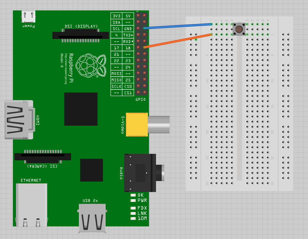
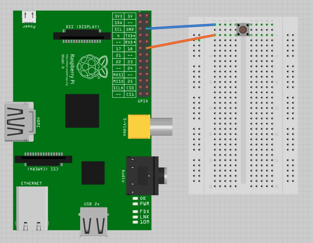
shows how to connect a tactile push switch, using a breadboard and jumper wires.
[visitor]
Click here to view Block Diagram (Free Registration )
[/visitor]
[member]
Open an editor (nano or IDLE) and paste in the following code.
This example code displays a message when the button is pressed:
[visitor]
Click here to view code (Free Registration )
[/visitor]
[member] importRPi.GPIOasGPIOimporttimeGPIO.setmode(GPIO.BCM)GPIO.setup(18,GPIO.IN,pull_up_down=GPIO.PUD_UP)whileTrue:input_state=GPIO.input(18)ifinput_state==False:('Button Pressed')time.sleep(0.2)
You will need to run the program as superuser:
pi@raspberrypi ~ $ sudo python switch.py
Button Pressed
Button Pressed
Button Pressed
Button Pressed
[/member]
Discussion
You will notice that the switch is wired so that when it is pressed, it will connect pin 18 configured as an input to GND. The input pin is normally pulled up to 3.3V by the optional argumentpull_up_down=GPIO.PUD_UP in GPIO.setup. This means that when you read the input value using GPIO.input, False will be returned if the button is pressed. This is a little counterintuitive.
Each GPIO pin has software configurable pull-up and pull-down resistors. When using a GPIO pin as an input, you can configure these resistors so that one or either or neither of the resistors is enabled, using the optional pull_up_down parameter to GPIO.setup. If this parameter is omitted, then neither resistor will be enabled. This leaves the input floating, which means that its value cannot be relied upon and it will drift between high and low depending on what it picks up in the way of electrical noise.
If it is set to GPIO.PUD_UP, the pull-up resistor is enabled; if it is set to GPIO.PUD_DOWN, the pull-down resistor is enabled.
You might expect the push switch to have just two connections, which are either open or closed. While some of these tactile push switches do have just two connections, most have four. shows how these connections are arranged.

Actually, there are only really two electrical connections, because inside the switch package pins B and C are connected together, as are A and D.
Source : http://razzpisampler.oreilly.com/


Post Comment
You must be logged in to post a comment.