EG MECH ROOM
buy oldham coupling, explain oldham coupling, generalized oldham coupling, homemade oldham coupling, how does oldham coupling work, how oldham coupling works, how to draw oldham coupling in catia, john oldham coupling, large oldham coupling, lovejoy oldham coupling, nbk oldham coupling, norton oldham coupling, oldham coupling 3d model, oldham coupling advantages, oldham coupling analysis, oldham coupling angular misalignment, oldham coupling animation, oldham coupling apparatus, oldham coupling applications, oldham coupling are used for, oldham coupling assembly, oldham coupling assembly drawing, oldham coupling australia, oldham coupling backlash, oldham coupling cad, oldham coupling cad model, oldham coupling calculation, oldham coupling catalog, oldham coupling catalogue, oldham coupling catia, oldham coupling cnc, oldham coupling definition, oldham coupling description, oldham coupling design, oldham coupling design procedure, oldham coupling dimensions, oldham coupling disadvantages, oldham coupling disc, oldham coupling diy, oldham coupling drawing, oldham coupling efficiency, oldham coupling equations, oldham coupling example, oldham coupling experiment, oldham coupling for sale, oldham coupling gif, oldham coupling history, oldham coupling hub, oldham coupling huco, oldham coupling hyundai, oldham coupling images, oldham coupling in catia, oldham coupling in scroll compressor, oldham coupling india, oldham coupling indonesia, oldham coupling information, oldham coupling is used for, oldham coupling is used to connect two shafts, oldham coupling kinematics, oldham coupling lego, oldham coupling limitations, oldham coupling linkage, oldham coupling lubrication pump, oldham coupling manufacturer, oldham coupling manufacturer in india, oldham coupling material, oldham coupling mechanism, oldham coupling mechanism animation, oldham coupling mechanism application, oldham coupling mechanism application, oldham coupling mechanism pdf, oldham coupling mechanism ppt, oldham coupling mechanism video, oldham coupling mechanism wiki, oldham coupling mechanism wiki, oldham coupling misalignment, oldham coupling parts, oldham coupling pdf, oldham coupling pdf, oldham coupling ppt, oldham coupling ppt free, oldham coupling price, oldham coupling principle, oldham coupling problems, oldham coupling problems, oldham coupling project, oldham coupling purpose, oldham coupling purpose, oldham coupling scroll compressor, oldham coupling singapore, oldham coupling sizes, oldham coupling sizes, oldham coupling sketch, oldham coupling solidworks, oldham coupling solidworks, oldham coupling specifications, oldham coupling suppliers, oldham coupling theory, oldham coupling theory, oldham coupling torque, oldham coupling types, oldham coupling types, oldham coupling uk, oldham coupling uses, oldham coupling video, oldham coupling video, oldham coupling wikipedia, oldham coupling working, oldham coupling youtube, oldham coupling youtube, oldham coupling zero backlash, oldham coupling zero backlash, oldham drive coupling, oldham flex coupling, oldham flexible coupling, oldham flexible coupling, oldham shaft coupling, oldham style coupling, oldham type flexible coupling, oldham's coupling, oldham's coupling, ruland oldham coupling, where oldham coupling is used
Keval Chaudhari
0 Comments
Mechanical Engineering : Oldham Coupling
Oldham Coupling
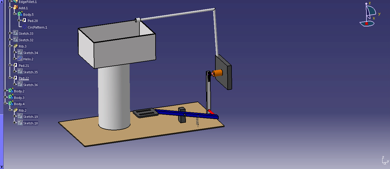
It is used to join two shafts which have lateral mis-alignment. It consists of two flanges A and B with slots and a central floating part E with two tongues T1 and T2 at right angles as shown in Fig. 1. The central floating part is held by means of a pin passing through the flanges and the floating part. The tongue T1 fits into the slot of flange A and allows for ‘to and fro’ relative motion of the shafts, while the tongue T2 fits into the slot of the flange B and allows for vertical relative motion of the parts. The resultant of these two components of motion will accommodate lateral misalignment of the shaft as they rotate.
An Oldham coupling has three discs, one coupled to the input, one coupled to the output, and a middle disc that is joined to the first two by tongue and groove. The tongue and groove on one side is perpendicular to the tongue and groove on the other. The middle disc rotates around its center at the same speed as the input and output shafts. Its center traces a circular orbit, twice per rotation, around the midpoint between input and output shafts. Often springs are used to reduce backlash of the mechanism. An advantage to this type of coupling, as compared to two universal joints, is its compact size. The coupler is named for John Oldham who invented it in Ireland, in 1821, to solve a in a paddle steamer design.
Reference A Text book of a Machine Design by R. S. Khurmi and J. K. Gupta and wiki pedia
Post Comment
You must be logged in to post a comment.