MECHANICS OF METAL CUTTING
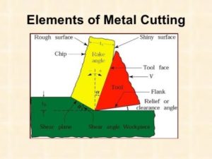
Metal cutting operation is illustrated in Fig. The work piece is securely clamped in a machine tool vice or clamps or chuck or collet. A wedge shape tool is set to a certain depth of cut and is forced to move in direction as shown in figure. All traditional machining processes require a cutting tool having a basic wedge shape at the cutting edge.
The tool will cut or shear off the metal, provided
(i) the tool is harder than the metal,
(ii) the tool is properly shaped so that its edge can be effective in cutting the metal,
(iii) the tool is strong enough to resist cutting pressures but keen enough to sever the metal, and
(iv) provided there is movement of tool relative to the material or vice versa, so as to make cutting action possible.
Most metal cutting is done by high speed steel tools or carbide tools. In metal cutting, the tool does not slide through metal as a jack knife does through wood, not does the tool split the metal as an axe does a log. Actually, the metal is forced off the work piece by being compressed, shearing off, and sliding along the face of the cutting tool. The way a cutting tool cuts the metal can be explained as follows. All metals in the solid state have a characteristic crystalline structure, frequently referred to as grain structure. The grain or crystals vary in size from very fine to very coarse, depending upon the type of metal and its heat-treatment. The cutting tool advances again in the work piece. Heavy forces are exerted on the crystals in front of the tool face.
These crystals, in turn exert similar pressures on crystals ahead of them, in the direction of the cut or force applied by the cutter. As the tool continues to advance, the material at sheared point is sheared by the cutting edge of the tool or it may be torn loose by the action of the bending chip which is being formed. As the tool advances, maximum stress is exerted along sheared line, which is called the shear plane. This plane is approximately perpendicular to the cutting face of the tool. There exists a shear zone on both sides of the shear plane, when the force of the tool exceeds the strength of the material at the shear plane, rupture or slippage of the crystalline grain structure occurs, thus forming the metal chip. The chip gets separated from the work piece material and moves up along the tool face. In addition, when the metal is sheared, the crystals are elongated, the direction of elongation being different from that of shear. The circles which represent the crystals in the uncut metal get elongated into ellipses after leaving the shearing plane. Source A Textbook of Basic Manufacturing Processes and Workshop Technology by Rajender Singh.


Post Comment
You must be logged in to post a comment.