Mini audio amplifier design |
This mini audio amplifier design will test the audio stages in amplifiers such as the front end of FM bugs. You can also use it on lots of our other projects as well as the output stages of radios. It is a very handy piece of test equipment and will make a perfect addition to your collection.
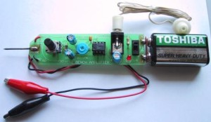
MINI AUDIO AMPLIFIER DESIGN
Some of the projects you can test with the Mini Bench Amplifier are tone circuits while others are audio circuits. Tone circuits and audio stages are surprisingly difficult to test unless you have an audio probe or a CRO.
A CRO is an ideal piece of equipment but if your budget does not extend this far, the next best thing is an audio probe.
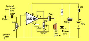
MINI AUDIO AMPLIFIER DESIGN CIRCUIT
There are lots of things that can go wrong with an audio stage. It can produce distortion or a “hollow” sound, go weak or simply fail altogether.
Likewise tone circuits can present a number of faults and it is very handy to be able to “hear” what is going wrong.
It is not sufficient to measure the DC voltages on these stages. This only gives a partial picture of the conditions and does not tell you the quality of the audio being processed. To determine this you need a piece of test equipment that will let you see or hear what is being processed.
Firstly we will cover the benefits and problems of using a CRO.
The main problem with seeing the waveform on a CRO is you have to interpret what you see and work out if distortion is present and where it is coming from. Believe me, this is harder to do than you think.
Let me give some examples from a TV service-man friend. He has serviced some 35,000 TV sets over a period of 15 years and in that time he has used a CRO on a number of occasions to try and find faults in audio stages.
One particularly troublesome audio fault occurred in an old black and white TV set, so he got out the CRO to try and solve the problem.
The audio was weak and distorted but since the signals around IF transformers are very small even when the circuit is functioning correctly, he could not locate the fault.
Audio waveforms are seldom shown on circuit diagrams and it is difficult to know if the signal you are viewing on a CRO is faulty or correct.
To fix the set he had to resort to the old tried-and-proven method of replacing components one-by-one. The fault turned out to be a 100p styro in one of the sound-IF cans. It had gone open-circuit and reduced the audio. But the CRO didn’t pick it up.
There were other occasions when he tried to use the CRO but the result was the same. It didn’t really help.
If you are a highly qualified audio technician and know the waveforms you should be getting at each location, it will be a completely different situation to trying to find an unknown fault in an audio stage. Sometimes an audio waveform is very messy when viewed on a CRO and yet the audio is quite clean. Other times the waveform appears to be quite good and yet the signal is distorted.
If the CRO was the answer to these problems, I would have no hesitation in suggesting you buy one, but it can sometimes create more problems than it solves.
To produce an audio waveform suitable for viewing on a CRO, you have to inject the stage with a steady waveform such as from a function generator or sine-wave oscillator. You cannot simply supply it with a signal from a radio station as the signal will be varying in amplitude and changing in frequency. The CRO will not be able to “lock in” and produce a stationary waveform.
You cannot work on a display that is constantly moving. This type of display is only suitable for amusement at a science exhibition. The screen must be perfectly stationary so you can view it and take measurements.
You need to measure the output and compare it to the input.
This is where a dual trace CRO comes in handy. On this type of CRO you will be able to display both the input and output at the same time and by super-imposing them on top of each other. You will then be able to see the differences.
Alternatively you can display one waveform above the other and pick out the differences.
If you only have a single trace CRO, you will need to switch from the input to output as quickly as possible so the differences can be detected.
Even when you see a difference you will have to work out if it represents a fault.
An audio stage does not always produce distortion due to clipping or over-drive, it sometimes sounds `hollow’ or `tinny’ due to the coupling capacitors being too small or dried out. These types of faults will not be picked up on a CRO and I suggest you save your money at this stage.
It will enable you fix audio faults very easily and save you a lot of frustration.
THE LM 386
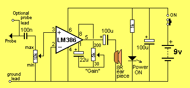
The LM 386 is a high power op-amp. It is used to drive a speaker. The inverting input has been connected to the negative rail and the non-inverting input has been connected to a capacitor. Resistors inside the chip bias this input so that it only requires about 7mV before the chip turns on. This voltage is called the off-set voltage.
When a signal is applied to the “+” input, the chip amplifies the waveform and the result appears on pin 5. The gain of the chip depends on the impedance of the path between pins 1 and 8. We have placed a variable impedance, made up of a 22u and 10k pot between these pins and by varying the resistance of the pot, the gain of the chip will be adjusted.
The gain can be adjusted from 30 to 200 and these figures are shown on the overlay of the board.
FIXING AUDIO STAGES
As we said, there can be lots of problems with audio stages. Sometimes they develop over a period of time, or they can be present from the moment the amplifier is assembled. You can also get intermittent faults, drop outs, squealing, motor-boating, distortion or simply lack of gain.
The amplifier presented in this article is used as an audio probe by listening to the loudness and quality of the audio going into the stage under test and comparing it to the audio emerging from the output of the stage.
You do this by putting the earpiece near your ear and listening carefully – that’s why the probe has two long leads.
We could write a book on fixing audio stages but to reduce it to one page, here is the approach:
The simplest situation is a single transistor amplifier with a distorted output.
The first thing to do is replace the transistor. Even though transistors are very reliable devices, you may have overheated it and this will cause the device to have a different gain and thus the voltages on the stage will not allow the signal to be processed correctly (you can put it back later if it is not the cause of the problem).
The next thing is measure the voltage on the collector. Ideally it should be half-rail. This allows the transistor to turn on and off THE MAXIMUM AMOUNT and thus give the stage the maximum gain.
To carry out any more investigation on the stage you will need a copy of the circuit diagram. This will let you know how the transistor is biased and may give details of the voltages at the various locations.
Next look at the electrolytics. These can be inter-stage devices, decoupling or emitter bypass capacitors. They can dry-out and lose their capacitance or go open (very rarely) or go short-circuit (very rare). Tantalums can also go short-circuit as they are susceptible to high voltage spikes that puncture their ceramic substrate.
If the transistor has an emitter by-pass capacitor in the form of an electrolytic across the emitter resistor, the stage gain will be severely reduced if the capacitor (electrolytic) has lost its capacitance (dried out).
A faulty inter-stage capacitor (one that connects the output of one stage to the input of the next) can be checked by placing the probe one side of the capacitor, then the other. If the audio level drops considerably, the capacitor is not passing the signal and may be faulty.
If you have replaced the transistor with another type, the voltage on the collector may be different to that specified.
If it is lower, the transistor has a higher gain and the base-bias resistor must be increased. If it is higher than expected, the base-bias resistor must be decreased.
This only applies to simple self-biasing stages, where the base-bias resistor sets the collector voltage for the stage.
Resistors rarely give trouble except if they are of an old style or in a position where they get hot.
If hum is present on the audio, the fault will lie in the filtering of the power supply. If a squeal similar to a feed-back squeal, (as heard when a microphone is too near the speaker of an amplifier), the fault can be in the decoupling capacitor. This is generally a small value electrolytic (10u to 100u) near the stage it is protecting and will be associated with a low value resistor on the power rail. The electrolytic is connected across the power rails.
This electrolytic can also produce a fault similar to the putt-putt-putt of a motor boat exhaust system, bubbling through water.
The Mini Bench Amp has a volume control in the form of a gain control, to vary the output volume from the earpiece. The approximate gain is marked around the control.
An additional probe can be connected to the board via a small socket and this will allow the Mini Amplifier to be brought up to your ear so you can listen to the audio.
CONSTRUCTION
Everything fits on the PC board supplied in the kit. The earpiece is plugged into a mono socket on the board.
|
|
|
The Mini AUDIO Amplifier artwork |
The IC socket is fitted so that the notch at one end corresponds to pin 1 and covers the cut-out on the overlay. This helps when fitting the IC at the end of assembly.
The cathode of the LED is identified by a flat side on the body of the LED and this is the line on the symbol on the overlay.
| 1 – 1k 1 – 5k mini pot with shaft 1 – 10k horizontal trim pot 1 – 100n monoblock capacitor 1 – 22u 16v PC mount electrolytic 2 – 100u 16v PC mount electrolytic 1 – LM 386 N1 400mW amp chip 1 – 8 pin IC socket 1 – 8R earpiece 1 – 3mm red LED 1 – battery snap 1 – 9v battery 1 – SPDT slide-switch 1 – mono, switched 2.5mm socket 1 – paper clip or long nail for probe 1 – black alligator clip 1 – red alligator clip 1 – 25cm red hook-up wire 1 – 25cm black hook-up wire 1 – pin and socket for lead 1 – MINI BENCH AMP PC Board |
The three electrolytics have a line down one side indicating the negative lead. The board has the positive lead marked with a small plus (“+”) sign.
The only other item needing a little care is the battery snap. It is removed from the plastic covering and the two lengths of wire snipped off, the two eyelets are tightened by hammering with a centre-punch. It is then fitted as shown in the following three diagrams:
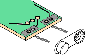 |
Fig1a. The bottom of the board is shown. The wire is looped from the bottom and twisted. Note the polarity of the battery snap. |
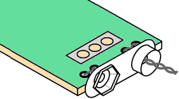 |
Fig1b. The battery snap is pushed up to the board and the twisted wires are cut short. |
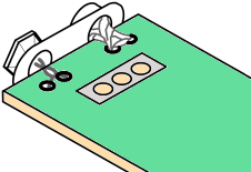 |
Fig1c. Both the top and bottom of the board are soldered to the battery snap to keep it firmly in position. |
The 9v battery is clipped directly to the board via the battery snap.
The optional probe uses red hookup wire and an alligator clip otherwise use a paper-clip or nail soldered to the end of the board.
The paper clip must not be cut with side-cutters as it is made from hardened steel and will damage the cutters. The only way to cut the clip is to file a niche in the wire and bend it back and forth until it fractures. This probe is then soldered directly to the board with some wire loops that add strength. It is called the active lead as it goes to the ‘active’ input of the chip.
The ground lead uses the black hook-up wire and has an alligator clip soldered to it.
All the other components are fitted close to the board and leads are snipped close to the board after soldering. Fit the IC and 9v battery and the project is complete.
IF IT DOESN’T WORK
Switch the Mini Bench Amp on and turn the gain control to maximum. Touch the active probe with your finger. You should hear a slight buzz from the speaker. This is a quick test to show the project is working. If nothing is detected, you should follow these steps:
If the power LED doesn’t come on, the most probable cause is a flat battery or the battery terminals not making contact.
Also check the placement of the LED as it may be around the wrong way.
Next check the current taken by the circuit, across the switch (with the switch in the OFF position). It should be about 10mA.
If no sound comes from the earpiece, measure its resistance with a multimeter. It should produce a slight `click’ when you do this and measure about 8 ohms.
Check that pin 1 of the IC is near the cut-out on the overlay and see that all the pins of the chip are entering the socket. Sometimes a pin bends over and does not make contact. Also make sure all the pins of the socket are soldered to the board. This applies to all the other components. Finally, make sure the positive of the battery goes to the positive rail on the board and the negative goes to the negative rail.
There is little else that can go wrong and the project should be working by now.
USING THE MINI BENCH AMP
All you have to do is connect the ground lead to the project you are testing, switch the Mini Bench Amp on and also the project you are testing. Use the probe or the active lead to probe various points on the project under test and listen for the audio. The gain control on the Mini Bench Amp is very similar to a volume control and will allow you to hear the audio without too much over-drive.
Most amplifying stages have a gain of about 50 – 70. Some will have a gain of about 100 but this is about as high as you will get.
It is impossible to describe how to determine if a stage has high or low gain, merely by listening to it. The only way to work out a gain factor is to use a CRO.
One clever way to fault-find a project is to get another identical unit and compare one with the other.
To do this you need to set both beside each other and join the ground lines together. Turn them both ON and you can then probe each stage and compare one with the other.
If you have had the frustration of trying to diagnose an audio stage, you will find this project absolutely essential.


Post Comment
You must be logged in to post a comment.