Introduction
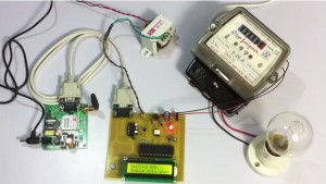
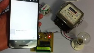
[nextpage title=”Introduction” ]The project provides a system that allows for consumed electricity reading in units as well as the amount charged over it to the user. Our system provides the electricity readings on an LCD screen as well as can sms this reading and cost in rupees to the user.
This lets the user know about his exact electricity units consumed and cost directly from his meter so that there is no chance of bill tampering. The project allows a two way reading. One on LCD display and the second on sms.
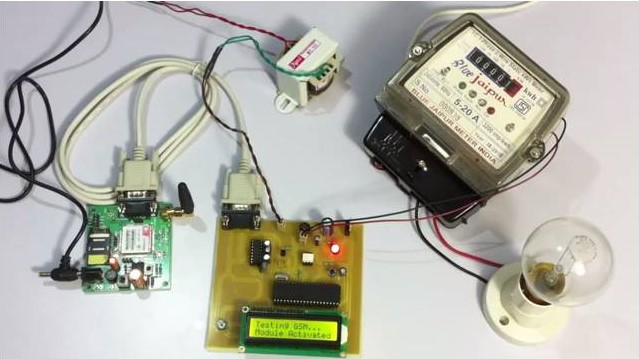
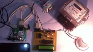
Our project consists of n gsm modem connected to a microcontroller of 8051 family. The system continuously monitors electrical pulses and calculates the unit consumption. The system then uses the cost of each unit to calculate the electricity cost.
It then sends all this data to user and electric company via sms and also displays it on an LCD screen for viewing. The system can be further enhanced to receive user messages and control load operations.[/nextpage]
Hardware and Software Specification
[nextpage title=”Hardware and Software Specification” ]
Hardware Specifications:
- 8051 series Microcontroller
- Level Shifter IC
- Opto Isolator
- GSM module
- Transformer
- LCD
- LED
- Crystal
- Diodes
- Regulator
- Energy Meter
- Lamp
Software Specifications:
- Keil µVision IDE
- MC Programming Language: Embedded C
opto-isolator:
Simple optoisolators consist of an LED and a photo transistor, embedded within a bit of plastic. Often that “bit of plastic” will hold more than one optoisolator. The following eight pin DIL package would have two independent optoisolators in it, for instance.
 The LED and phototransistor are not “connected”, but when the LED is on, light from it strikes the phototransistor inside a little pocket of air inside the opaque “bit of plastic”, and the phototransistor conducts. (In fancy optoisolators, the phototransistor may be replaced by something else that “switches on” when the LED illuminates it.) In the following, I’ve drawn the opto isolator in black, things you might attach to it in blue. At the green blob, you will get a high voltage or a low voltage, depending (indirectly) on the state of the LED, itself determined by the state of the switch.
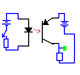 You won’t see the light from the LED… it will be inside the “bit of plastic.”
[/nextpage]


Post Comment
You must be logged in to post a comment.