Multimeter Tutorial: How to Test and Measure Resistance
Step 1: How to Use Multimeter
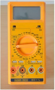
As its name suggests, a multimeter measures various circuit parameters such as resistance, voltage, current, and capacitance. More precision over multimeter readings can be achieved by using a digital output.Measurements of different ranges are marked on the DMM. These are the maximum values of measurementsup to which they can display.
- a) Power ON the DMM.
{C}b) {C}From the resistance color coding we framed out the theoretical value of resistance.
- c) Turn the knob to the ? or ohm section.
Step 2:Connecting Test Leads
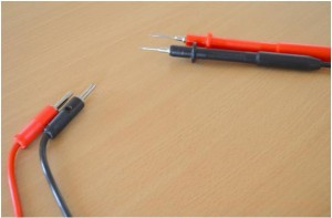
Following the standard color convention for leads,red colored lead is connected to the positive terminal of the multimeter and Black to the ground or COM terminal.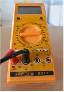
[tie_slideshow]
[tie_slide] Multimeter Tutorial: How to Test LED [/tie_slide]
[tie_slide] Multimeter Tutorial: How to Test a Transistor [/tie_slide]
[tie_slide] Multimeter Tutorial: How to Test and Measure Resistance [/tie_slide]
[/tie_slideshow]
Step 3:Creating connections
Crocodile teeth testing lead is added as an extension to the original leads.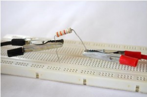
Since polarity is not an issue with resistors, the connected leads can be connected in any random manner. The output would be the same in every case.
Step 4:How to Measure Resistance using Multimeter
How to Measure Resistance using Multimeter
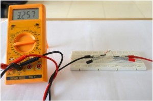
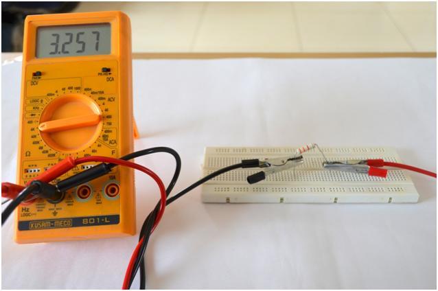
Digital Multimeter shows the reading 3.257 K ohm which is approximately same as the one suggested by the color coding of the resistor. Defective resistance will show reading below then its tolerance.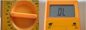
If we fix the knob at the value less than the resistance then the multimeter will show some error, in this case it shows OL which means over range.


Post Comment
You must be logged in to post a comment.