Astable multivibrator using op amp
Astable multivibrator is an electronic device which can continuously shift between its two states with respect to the output. If the output corresponding to one particular state is high, then the output corresponding to the other state is low. This nature of the circuit is useful in producing continuous output stream of pulses.
There is no need for external triggering in case of astable multivibrator circuits. Simply turn on the power and the circuit start oscillating between its two states. Since it is an oscillator, a positive feedback can be found in this kind of circuits also.
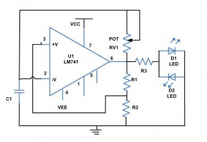
It is very easy to realize an astable multivibrator using op-amp ICs. The following circuit is an implementation of astable multivibrator using the 741 op-amp IC.

Op-amp multivibrator circuit
In the above circuit, you can see a positive feedback introduced into the non-inverting pin of the 741 IC, after dividing the output voltage from pin6 using two resistors R1 and R2. There is a capacitor connected to the inverting pin of the op-amp. This capacitor charges through the pot RV1.
Initially the capacitor is uncharged condition, and we can expect 0V at the inverting pin of the op-amp. In this condition the output is high, and the non-inverting pin of the op-amp is getting a voltage, which is the output voltage divided by the two resistors. The capacitor starts charging to the high voltage of the output pin through the variable resistor RV1. While it is charging the potential at the inverting pin gradually increases. Eventually at some point of time, the voltage at the inverting pin reaches slightly above the voltage at the non-inverting pin. At this point of time the output of the op-amp goes low (negative) abruptly.
When the output pin becomes negative, the capacitor suddenly discharges to zero and then starts charging in the negative direction. While it charges in the negative direction, the output remains low since the non-inverting pin is getting a low voltage divided from the output pin. At some point of time the voltage at the inverting pin reaches below the voltage of the non-inverting pin and the output goes high (positive) abruptly.
Now the capacitor again discharges to zero and start doing the same procedure again. Thus we get a continuous pulse train at the output, and are indicated by the two LEDs.
Component specifications:
R1=R2=R3=1KE, 1/4W resistor
C1=10uf, 25V electrolytic capacitor
D1=LED (red), 3mm
D2=LED (green), 3mm
RV1=10K, variable resistor
U1=LM741
Component significance:
R1: The value of this resistor has significant effect in the time period of the output pulse. If you decrease this resistance, the output pulse’s time period increases and if you increase this resistance, the output pulse’s time period decreases.
R2: The pulse time period is directly depends on the value of this resistance. If you increase the resistance, the time period increases and if you decrease the resistance, the time period decreases.
R3: This resistance controls the brightness of the LEDs. Decreasing this resistance increases the brightness, and increasing this resistance decreases the brightness. The values above 220 ohms are safe to use with the LEDs.
C1: The output pulse time period keeps a direct proportionality with the value of this capacitance. If you increase the value, the time period increases and if you decrease the value the time period decreases.
RV1: The output pulse time period also has a direct proportionality with the value the resistance introduced by this variable resistance into the circuit. If you increase the resistance, the output time period increases and if you decrease the resistance, the output time period decreases.


Post Comment
You must be logged in to post a comment.