PRESSURE DIE CASTING
Unlike permanent mold or gravity die casting, molten metal is forced into metallic mold or die under pressure in pressure die casting. The pressure is generally created by compressed
air or hydraulically means. The pressure varies from 70 to 5000 kg/cm2 and is maintained while the casting solidifies. The application of high pressure is associated with the high velocity with which the liquid metal is injected into the die to provide a unique capacity for the production of intricate components at a relatively low cost. This process is called simply die casting in USA. The die casting machine should be properly designed to hold and operate a die under pressure smoothly. There are two general types of molten metal ejection mechanisms adopted in die casting set ups which are:
(i) Hot chamber type
(a) Gooseneck or air injection management
(b) Submerged plunger management
(ii) Cold chamber type
Die casting is widely used for mass production and is most suitable for non-ferrous metals and al1oys of low fusion temperature. The casting process is economic and rapid. The
surface achieved in casting is so smooth that it does not require any finishing operation. The material is dense and homogeneous and has no possibility of sand inclusions or other cast impurities. Uniform thickness on castings can also be maintained.
The principal base metals most commonly employed in the casting are zinc, aluminum, and copper, magnesium, lead and tin. Depending upon the melting point temperature of alloys and their suitability for the die casting, they are classified as high melting point (above 540°C) and low melting point (below 500°C) alloys. Under low category involves zinc, tin and lead base alloys. Under high temperature category aluminum and copper base alloys are involved. There are four main types of die-casting machine which are given as under.
1. Hot chamber die casting machine
2. Cold chamber die casting machine.
3. Air blown or goose neck type machine
4. Vacuum die-casting machine
Some commonly used die casting processes are discussed as under.
Hot chamber die-casting
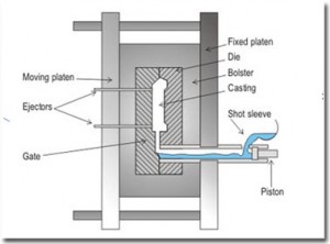
Hot chamber die-casting machine is the oldest of die-casting machines which is simplest to operate. It can produce about 60 or more castings of up to 20 kg each per hour and several hundred castings per hour for single impression castings weighing a few grams. The melting unit of setup comprises of an integral part of the process. The molten metal possesses nominal amount of superheat and, therefore, less pressure is needed to force the liquid metal into the die. This process may be of gooseneck or air-injection type or submerged plunger type-air blown or goose neck type machine is shown as in Fig. It is capable of performing the following functions:
(i) Holding two die halves finally together.
(ii) Closing the die.
(iii) Injecting molten metal into die.
(iv) Opening the die.
(v) Ejecting the casting out of the die.
A die casting machine consists of four basic elements namely frame, source of molten metal and molten metal transfer mechanism, die-casting dies, and metal injection mechanism.
It is a simple machine as regards its construction and operation. A cast iron gooseneck is so pivoted in the setup that it can be dipped beneath the surface of the molten metal to receive the same when needed. The molten metal fills the cylindrical portion and the curved passageways of the gooseneck. Gooseneck is then raised and connected to an airline which supplies pressure to force the molten metal into the closed die. Air pressure is required for injecting metal into the die is of the order of 30 to 45 kg./cm2. The two mold halves are securely clamped together before pouring. Simple mechanical clamps of latches and toggle kinds are adequate for small molds. On solidification of the die cast part, the gooseneck is again dipped beneath the molten metal to receive the molten metal again for the next cycle. The die halves are opened out and the die cast part is ejected and die closes in order to receive a molten metal for producing the next casting. The cycle repeats again and again. Generally large permanent molds need pneumatic or other power clamping devices. A permanent mold casting may range in weight from a few grams to 150 kg. for aluminum. Cores for permanent molds are made up of alloy steel or dry sand. Metal cores are used when they can be easily extracted from the casting. A dry sand core or a shell core is preferred when the cavity to be cored is such that a metal core cannot possibly be withdrawn from the casting. The sprues, risers, runners, gates and vents are machined into the parting surface for one or both mold halves.
The runner channels are inclined, to minimize turbulence of the incoming metal. Whenever possible, the runner should be at the thinnest area of the casting, with the risers at the top of the die above the heavy sections. On heating the mold surfaces to the required temperature, a refractory coating in the form of slurry is sprayed or brushed on to the mold cavity, riser, and gate and runner surfaces. French chalk or calcium carbonate suspended in sodium silicate binder is commonly used as a coating for aluminum and magnesium permanent mold castings. Chills are pieces of copper, brass or aluminum and are inserted into the mold’s inner surface. Water passages in the mold or cooling fins made on outside the mold surface are blown by air otherwise water mist will create chilling effect. A chill is commonly used to promote directional solidification. Copied from A Basic Manufacturing Processes and Workshop Technology by Rajender Singh.


Post Comment
You must be logged in to post a comment.