Introduction:
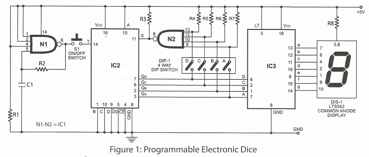
Dice game is very interesting indoor game mostly played in childhood. Here is verified game project programmable electronics dice useful in many game. With the help of this project we can display any number between 1 to 9 according to our dip switch setting.
Circuit description of programmable electronics dice
The project programmable electronics dice comprises three ICs as heart and for output a common anode display. Here, IC1 used is a dual 4-input Schmitt trigger NAND gate IC where gate N1 used as frequency generator which generate the clock frequency of 70kHz with the help of resistor R2 and capacitor C1 and gate N2 load data at the input of IC2. Where IC2 is a presettable binary counter with the facilities of parallel loading. Lastly the output of IC2 is displayed on common-anode, 7-segmant display with the help of IC3 which is BCD-to-7-segmant decoder and the resistor R8 is used as current limiter.
Setting for the 4-way DIP switch for display range
| Dice Range | Close the inner switch | Open the inner switch |
| 1 to 2 | B and A | D and C |
| 1 to 3 | C only | A, B and D |
| 1 to 4 | A and C | B and D |
| 1 to 5 | B and C | A and D |
| 1 to 6 | A, B and C | D only |
| 1 to 7 | D only | A, B and C |
| 1 to 8 | A and D | B and C |
| 1 to 9 | B and D | A and C |
PARTS LIST
Resistors (all ¼-watt, ± 5% Carbon)
- R1 = 1 KΩ
- R2 = 100 Ω
- R3 – R7 = 4.7 KΩ
- R8 = 220 Ω
Capacitor
- C1 = 0.1 µF
Semiconductors
- IC1 = 74LS13, dual 4-input Schmitt trigger NAND gate IC
- IC2 = 74LS191, presettable binary counter with parallel facility
- IC3 = 7474, BCD-to-7-segmant decoder
Miscellaneous
- DIS-1 = LTS542 common anode display of equivalent
- SW1 = ON/OFF switch
- SW2 = 4-way dip switch


Post Comment
You must be logged in to post a comment.