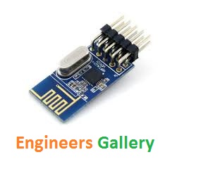
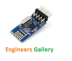
The RF module, as the name suggests, operates at Radio Frequency. The corresponding frequency range varies between 30 kHz & 300 GHz. In this RF system, the digital data is represented as variations in the amplitude of carrier wave. This kind of modulation is known as Amplitude Shift Keying (ASK).
Transmission through RF is better than IR (infrared) because of many reasons. Firstly, signals through RF can travel through larger distances making it suitable for long range applications. Also, while IR mostly operates in line-of-sight mode, RF signals can travel even when there is an obstruction between transmitter & receiver. Next, RF transmission is more strong and reliable than IR transmission. RF communication uses a specific frequency unlike IR signals which are affected by other IR emitting sources.
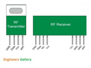
This RF module comprises of an RF Transmitter and an RF Receiver. The transmitter/receiver (Tx/Rx) pair operates at a frequency of 434 MHz. An RF transmitter receives serial data and transmits it wirelessly through RF through its antenna connected at pin4. The transmission occurs at the rate of 1Kbps – 10Kbps.The transmitted data is received by an RF receiver operating at the same frequency as that of the transmitter.
The RF module is often used alongwith a pair of encoder/decoder. The encoder is used for encoding parallel data for transmission feed while reception is decoded by a decoder. HT12E-HT12D, HT640-HT648, etc. are some commonly used encoder/decoder pair ICs.
Pin Description:
RF Transmitter
| Pin No | Function | Name |
| 1 | Ground (0V) | Ground |
| 2 | Serial data input pin | Data |
| 3 | Supply voltage; 5V | Vcc |
| 4 | Antenna output pin | ANT |
RF Receiver
| Pin No | Function | Name |
| 1 | Ground (0V) | Ground |
| 2 | Serial data output pin | Data |
| 3 | Linear output pin; not connected | NC |
| 4 | Supply voltage; 5V | Vcc |
| 5 | Supply voltage; 5V | Vcc |
| 6 | Ground (0V) | Ground |
| 7 | Ground (0V) | Ground |
| 8 | Antenna input pin | ANT |


Post Comment
You must be logged in to post a comment.