Title: Study of Scotch Yoke Mechanism
OBJECTIVE:
To gain in-depth practical knowledge and to improve the Understanding of the mechanism
RESOURCES REQUIRED:
1)Model of scotch yoke
2)class notes
3)Text book
4)Ruler
5)Vernier calipers
THEORY:
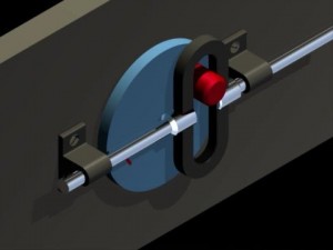
Scotch yoke is a mechanism used to convert rotary motion into Sliding motion. This mechanism is obtained from an inversion of the double Slider crank chain.
Double slider crank chain is a four-bar kinematic chain having 2 sliding Pairs and 2 turning pairs such that two pairs of the same kind are adjacent. The general version of the double slider crank chain is shown in fig. 1. two Die-blocks, P & Q, slide along slots in a frame, and the pins P & Q on the Die-blocks are connected by a link PQ

[sam id=”4″ codes=”true”]
This inversion is obtained by fixing one of the sliders. Refer fig. 2. let Slider block ‘p’ be fixed. Link PQ may then rotate relative to die blocks about The pins P & Q. thus link PQ can rotate with pin P as centre, and will therefore Cause the frame to reciprocate along the axis passing through P, slider block ‘Q’ will also reciprocate in its slot. The stroke of the frame will depend upon the length of link PQ and will be double the length PQ.
Description of the model:
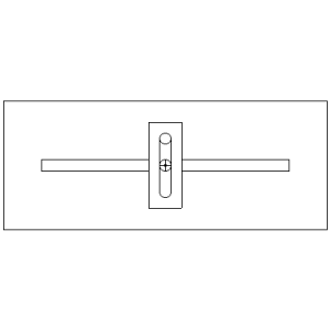
A model of scotch yoke mechanism is to be used for study. A diagram of the Model is shown in fig .4. the model consist of a slider plate guides G1 and G2 Mounted on the base plate of the model. The slider plate carries a slot AB in Which a slider block ‘Q’ as centre, and drives the slider block Q. arm OR. the Arm OR is free to rotate about point ‘O’ as centre, and drives the slider block ‘Q’. The position of point ‘R’ can be changed by selecting one of the four holes Provided on the arm OR and shifting the screw to the particular hole. The
Crank OR is further rigidly linked to a handle which is used to provide manual Rotation to the link, and thereby impart motion to the mechanism. An extension To the rotating arm OR is provided which carries a pencil to trace the movement Of the arm.
Precaution :
- Handle the model with care and attention. The model should not be mishandled
- It should not be dismantled, unless for a specific purpose and then also,only with the permission of the lab I/c.
- The moving parts of the model must be lubricated as and when necessary.
- Defect,if any, noticed in the model must be brought to the attention of the Lab I/c immediately.
- All measurements must be made with sufficient precision, and must be verified by making repeated measurements. An average value of the measurements must be taken to be the true value of the parameter.
Experiment: the student is expected to conduct the following:
- Study the construction of the model of scotch yoke.
- Study the movement of the slider plate as the drive shaft is rotated.
- Trace the path of the crank, and record the motion of the slider plate for different sizes of the crank by changing the link OR. Make measurements to determine the diameter of the circular path described by the actual stroke of slider plate.
- To search animations of this mechanism on the internet and study the same for a better understanding of the principles involved.Result:
- State the measurements and the derived values along with the actual values.
- State the animation studied and its source.


Post Comment
You must be logged in to post a comment.