BEVEL GEAR
Two important concepts in gearing are pitch surface and pitch angle. The pitch surface of a gear is the imaginary toothless surface that you would have by averaging out the peaks and valleys of the individual teeth. The pitch surface of an ordinary gear is the shape of a cylinder. The pitch angle of a gear is the angle between the face of the pitch surface and the axis.
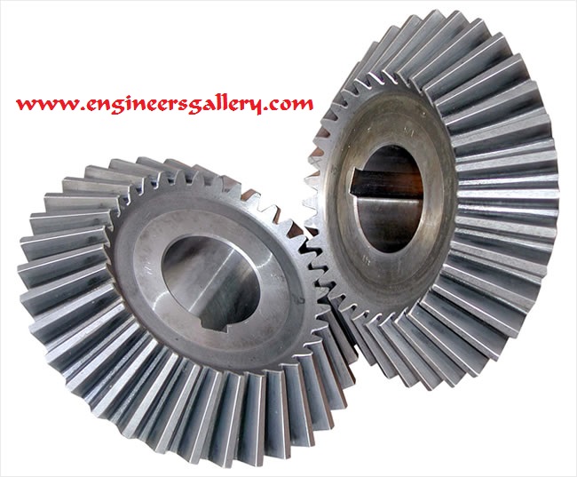
The most familiar kinds of bevel gears have pitch angles of less than 90 degrees and therefore are cone-shaped. This type of bevel gear is called external because the gear teeth point outward. The pitch surfaces of meshed external bevel gears are coaxial with the gear shafts; the apexes of the two surfaces are at the point of intersection of the shaft axes.

Bevel gears that have pitch angles of greater than ninety degrees have teeth that point inward and are called internal bevel gears.
Bevel gears that have pitch angles of exactly 90 degrees have teeth that point outward parallel with the axis and resemble the points on a crown. That’s why this type of bevel gear is called a crown gear.
Miter gears are mating bevel gears with equal numbers of teeth and with axes at right angles.
Skew bevel gears are those for which the corresponding crown gear has teeth that are straight and oblique.
Bevel gears are classified in different types according to geometry:
- Straight bevel gears have conical pitch surface and teeth are straight and tapering towards apex.
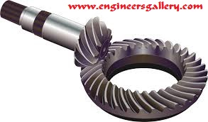
- Spiral bevel gears have curved teeth at an angle allowing tooth contact to be gradual and smooth.
- Zerol bevel gears are very similar to a bevel gear only exception is the teeth are curved: the ends of each tooth are co-planar with the axis, but the middle of each tooth is swept circumferential around the gear. Zerol bevel gears can be thought of as spiral bevel gears (which also have curved teeth) but with a spiral angle of zero (so the ends of the teeth align with the axis).
- Hypoid bevel gears are similar to spiral bevel but the pitch surfaces are hyperbolic and not conical. Pinion can be offset above, or below,the gear center, thus allowing larger pinion diameter, and longer life and smoother mesh, with additional ratios e.g., 6:1, 8:1, 10:1. In a limiting case of making the “bevel” surface parallel with the axis of rotation, this configuration resembles a worm drive.
- This gear makes it possible to change the operating angle.
- Differing of the number of teeth (effectively diameter) on each wheel allows mechanical advantage to be changed. By increasing or decreasing the ratio of teeth between the drive and driven wheels one may change the ratio of rotations between the two, meaning that the rotational drive and torque of the second wheel can be changed in relation to the first, with speed increasing and torque decreasing, or speed decreasing and torque increasing.
- High efficiency (can be 98% or higher), can transfer power across non-intersecting shafts. Spiral bevel gears transmit loads evenly and are quieter than straight bevel.
- One wheel of such gear is designed to work with its complementary wheel and no other.
- Must be precisely mounted.
- The shafts’ bearings must be capable of supporting significant forces.
Reference :
- Green Mechanic
- Wikipedia


Post Comment
You must be logged in to post a comment.