SPIRAL BEVEL GEAR
[nextpage title=”Description” ]
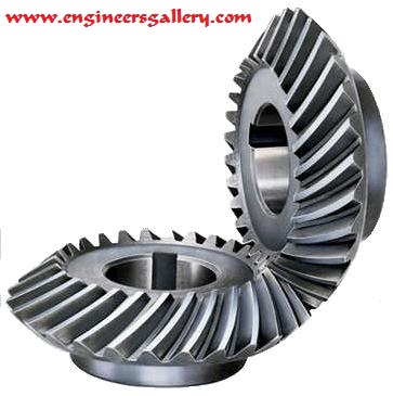
A spiral bevel gear is a bevel gear with helical teeth. The main application of this is in a vehicle differential, where the direction of drive from the drive shaft must be turned 90 degrees to drive the wheels. The helical design produces less vibration and noise than conventional straight-cut or spur-cut gear with straight teeth.
A spiral bevel gear set should always be replaced in pairs i.e. both the left hand and right hand gears should be replaced together since the gears are manufactured and lapped in pairs.

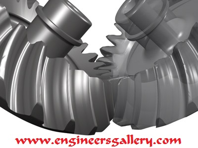
To understand the bevel gear tooth geometry, one might first observe the case of straight bevel gears. If the generating rack used to derive the cylindrical gear involute is bent in a horizontal plane into a circular shape, it results in a crown gear, which is used to derive the flank form of bevel pinion and gear. In the case of straight bevel gears, the crown gear or generating gear can be placed between the pinion and gear assembly.

[/nextpage]
[nextpage title=”Handedness” ]
Handedness
A right hand spiral bevel gear is one in which the outer half of a tooth is inclined in the clockwise direction from the axial plane through the midpoint of the tooth as viewed by an observer looking at the face of the gear.
A left hand spiral bevel gear is one in which the outer half of a tooth is inclined in the counterclockwise direction from the axial plane through the midpoint of the tooth as viewed by an observer looking at the face of the gear.
Note that a spiral bevel gear and pinion are always of opposite hand, including the case when the gear is internal.
Also note that the designations right hand and left hand are applied similarly to other types of bevel gear, hypoid gears, and oblique tooth face gears.
[/nextpage]
[nextpage title=”Hypoid Gears” ]
Hypoid gears
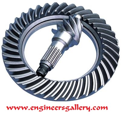
A hypoid is a type of spiral bevel gear whose axis does not intersect with the axis of the meshing gear. The shape of a hypoid gear is a revolved hyperboloid (that is, the pitch surface of the hypoid gear is a hyperbolic surface), whereas the shape of a spiral bevel gear is normally conical. The hypoid gear places the pinion off-axis to the crown wheel (ring gear) which allows the pinion to be larger in diameter and have more contact area. In hypoid gear design, the pinion and gear are practically always of opposite hand, and the spiral angle of the pinion is usually larger than that of the gear. The hypoid pinion is then larger in diameter than an equivalent bevel pinion.
A hypoid gear incorporates some sliding and can be considered halfway between a straight-cut gear and a worm gear. Specialgear oils are required for hypoid gears because the sliding action requires effective lubrication under extreme pressure between the teeth.
Hypoid gearings are used in power transmission products that are more efficient than conventional worm gearing. They are considerably stronger in that any load is conveyed through multiple teeth simultaneously. By contrast, bevel gears are loaded through one tooth at a time. The multiple contacts of hypoid gearing, with proper lubrication, can be nearly silent, as well.
[/nextpage]
[nextpage title=”Spiral angle” ]
Spiral angle
The spiral angle in a spiral bevel gear is the angle between the tooth trace and an element of the pitch cone, and corresponds to the helix angle in helical teeth. Unless otherwise specified, the term spiral angle is understood to be the mean spiral angle.
- Mean spiral angle is the specific designation for the spiral angle at the mean cone distance in a bevel gear.
- Outer spiral angle is the spiral angle of a bevel gear at the outer cone distance.
- Inner spiral angle is the spiral angle of a bevel gear at the inner cone distance.

[/nextpage]
Reference : Wikipedia


Post Comment
You must be logged in to post a comment.