INTRODUCTION
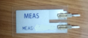
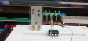 SHOCK SENSOR:
The piezo element vibration or pressure resulting electrical output of the sensor from constant pounding from the instant that a malzemedir.piezo rather than taking measurements, measuring the effects work like shock gives more reliable results. Therefore it is recommended to operate in this manner.
When the vibration sensor mV as a result of pressure applied on the s-level voltage increasing in many areas the OP-AMP circuit with .sens will remain under the influence – when the voltage applied + voltage in driving the z by the controller or analog input We can use it as.
741 OP-AMP CIRCUIT:
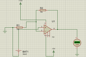
The voltage applied to an amplifier circuit 741 (supply voltage) is calculated by using resistors on while a voltage more account.
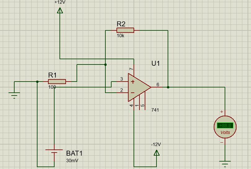
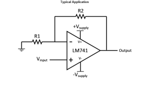 Here gain RF / R1 (a OPAMPs en top in this way so that inverting for inversion. – Input is connected to the end) Our circuit has RF: 10K stop R1 100 Ohms. So we gain RF / R1 to 100. This means that even the input signal will be upgraded applied 100 times.
CIRCUIT DIAGRAM:
30 mV DC supply instead of the vibration sensor is used in the circuit diagram.



Post Comment
You must be logged in to post a comment.