POWER OPERATED EQUIPMENTS
Power operated foundry equipments generally used in foundries are different types of molding machines and sand slingers, core making, core baking equipment, power riddles, mechanical conveyors, sand mixers, material handling equipment and sand aerators etc. Few commonly used types of such equipments are discussed as under.
1 Moulding Machines
Molding machine acts as a device by means of a large number of co-related parts and mechanisms, transmits and directs various forces and motions in required directions so as to help the preparation of a sand mould. The major functions of molding machines involves ramming of molding sand, rolling over or inverting the mould, rapping the pattern and withdrawing the pattern from the mould. Most of the molding machines perform a combination of two or more of functions. However, ramming of sand is the basic function of most of these machines. Use of molding machine is advisable when large number of repetitive castings is to be produced as hand molding may be tedious, time consuming, laborious and expensive comparatively.
2 Classification of Moulding Machines
The large variety of molding machines that are available in different designs which can be classified as squeezer machine, jolt machine, jolt-squeezer machine, slinging machines, pattern draw machines and roll over machines. These varieties of machines are discussed as under.
2.1 Squeezer machine
These machines may be hand operated or power operated. The pattern is placed over the machine table, followed by the molding box. In hand-operated machines, the platen is lifted by hand operated mechanism. In power machines, it is lifted by the air pressure on a piston in the cylinder in the same way as in jolt machine. The table is raised gradually. The sand in the molding box is squeezed between plate and the upward rising table thus enabling a uniform pressing of sand in the molding box. The main advantage of power operated machines in comparison hand operated machines is that more pressure can be applied in power operated.
2.2 Jolt machine
This machine is also known as jar machine which comprises of air operated piston and cylinder. The air is allowed to enter from the bottom side of the cylinder and acts on the bottom face of the piston to raise it up. The platen or table of the machine is attached at the top of the piston which carries the pattern and molding box with sand filled in it. The upward movement of piston raises the table to a certain height and the air below the piston is suddenly released, resulting in uniform packing of sand around the pattern in the molding box. This process is repeated several times rapidly. This operation is known as jolting technique.
3 Jolt-squeezer machine
It uses the principle of both jolt and squeezer machines in which complete mould is prepared. The cope, match plate and drag are assembled on the machine table in a reverse position, that is, the drag on the top and the cope below. Initially the drag is filled with sand followed by ramming by the jolting action of the table. After leveling off the sand on the upper surface, the assembly is turned upside down and placed over a bottom board placed on the table. Next, the cope is filled up with sand and is rammed by squeezing between the overhead plate and the machine table. The overhead plate is then swung aside and sand on the top leveled off, cope is next removed and the drag is vibrated by air vibrator. This is followed by removal of match plate and closing of two halves of the mold for pouring the molten metal. This machine is used to overcome the drawbacks of both squeeze and jolt principles of ramming molding sand.
2.4 Slinging machines
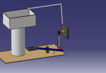
These machines are also known as sand slingers and are used for filling and uniform ramming of molding sand in molds. In the slinging operations, the consolidation and ramming are obtained by impact of sand which falls at a very high velocity on pattern. These machines are generally preferred for quick preparation of large sand moulds. These machines can also be used in combination with other devices such as, roll over machines and pattern draw machines for reducing manual operations to minimum. These machines can be stationary and portable types. Stationary machines are used for mass production in bigger foundries whereas portable type machines are mounted on wheels and travel in the foundry shop on a well planned fixed path. A typical sand slinger consists of a heavy base, a bin or hopper to carry sand, a bucket elevator to which are attached a number of buckets and a swinging arm which carries a belt conveyor and the sand impeller head. Well prepared sand is filed in a bin through the bottom of which it is fed to the elevator buckets. These buckets discharge the molding sand to the belt conveyor which conveys the same to the impeller head. This head can be moved at any location on the mold by swinging the arm. The head revolves at a very high speed and, in doing so, throws stream of molding sand into the molding box at a high velocity. This process is known as slinging. The force of sand ejection and striking into the molding box compel the sand gets packed in the box flask uniformly. This way the satisfactory ramming is automatically get competed on the mold. It is a very useful machine in large foundries.
2.5 Pattern draw machines
These machines enable easy withdrawal of patterns from the molds. They can be of the kind of stripping plate type and pin lift or push off type. Stripping plate type of pattern draw machines consists of a stationary platen or table on which is mounted a stripping plate which carries a hole in it. The size and shape of this hole is such that it fits accurately around the pattern. The pattern is secured to a pattern plate and the latter to the supporting ram. The pattern is drawn through the stripping plate either by raising the stripping plate and the mould up and keeping the pattern stationary or by keeping the stripping plate and mould stationary and moving the pattern supporting ram downwards along with the pattern and pattern plate. A suitable mechanism can be incorporated in the machine for these movements.
2.6 Roll-over machine
This machine comprises of a rigid frame carrying two vertical supports on its two sides having bearing supports of trunnions on which the roll-over frame of the machine is mounted. The pattern is mounted on a plate which is secured to the roll-over frame. The platen of the machine can be moved up and down. For preparation of the mould, the roll-over frame is clamped in position with the pattern facing upward. Molding box is placed over the pattern plate and clamped properly. Molding sand is then filled in it and rammed by hand and the extra molding sand is struck off and molding board placed over the box and clamped to it.
After that the roll-over frame is unclamped and rolled over through 180° to suspend the box below the frame. The platen is then lifted up to butt against the suspending box. The box is unclamped from the pattern plate to rest over the platen which is brought down leaving the pattern attached to the plate. The prepared mold is now lowered. The frame is then again rolled over to the original position for ramming another flask. Other mechanisms are always incorporated to enable the above rolling over and platen motion. Some roll-over machines may carry a pneumatic mechanism for rolling over. There are others mechanism also which incorporate a jolting table for ramming the sand and an air operated rocking arm to facilitate rolling over. Some machines incorporate a mechanically or pneumatically operated squeezing mechanism for sand ramming in addition to the air operated rolling over mechanism. All such machines are frequently referred to as combination machines to carry out the molding tasks automatically. Copied from A Textbook of Manufacturing processes and Workshop Technology by Rajender Singh.


