PRINCIPAL PARTS OF SHAPER
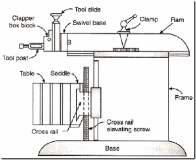
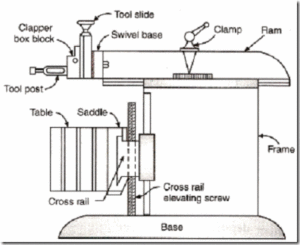
Fig. shows the parts of a standard shaper. The main parts are given as under.
1. Base
2. Column
3. Cross-rail
4. Saddle
5. Table
6. Ram
7. Tool head
8. Clapper box
9. Apron clamping bolt
10. Down feed hand wheel
11. Swivel base degree graduations
12. Position of stroke adjustment hand wheel
13. Ram block locking handle
14. Driving pulley
15. Feed disc
16. Pawl mechanism
17. Elevating screw
Some of important parts are discussed as under.
Base
It is rigid and heavy cast iron body to resist vibration and takes up high compressive load. It supports all other parts of the machine, which are mounted over it. The base may be rigidly bolted to the floor of the shop or on the bench according to the size of the machine.
Column
The column is a box shaped casting mounted upon the base. It houses the ram-driving mechanism. Two accurately machined guide ways are provided on the top of the column on which the ram reciprocates.
Cross rail
Cross rail of shaper has two parallel guide ways on its top in the vertical plane that is perpendicular to the rai1 axis. It is mounted on the front vertical guide ways of the column. It consists mechanism for raising and lowering the table to accommodate different sizes of jobs by rotating an elevating screw which causes the cross rail to slide up and down on the vertical face of the column. A horizontal cross feed screw is fitted within the cross rail and parallel to the top guide ways of the cross rail. This screw actuates the table to move in a crosswise direction.
Saddle
The saddle is located on the cross rail and holds the table on its top. Crosswise movement of the saddle by rotation the cross feed screw by hand or power causes the table to move
sideways.
Table
The table is a box like casting having T -slots both on the top and sides for clamping the work. It is bolted to the saddle and receives crosswise and vertical movements from the saddle and cross rail.
Ram
It is the reciprocating part of the shaper, which reciprocates on the guideways provided above the column. Ram is connected to the reciprocating mechanism contained within the column.
Tool head
The tool head of a shaper performs the following functions-
(1) It holds the tool rigidly,
(2) It provides vertical and angular feed movement of the tool, and
(3) It allows the tool to have an automatic relief during its return stroke.
The various parts of tool head of shaper are apron clamping bolt, clapper box, tool post, down feed, screw micrometer dial, down feed screw, vertical slide, apron washer, apron swivel pin, and swivel base. By rotating the down feed screw handle, the vertical slide carrying the tool gives down feed or angular feed movement while machining vertical or angular surface. The amount of feed or depth of cut may be adjusted by a micrometer dial on the top of the down feed screw. Apron consisting of clapper box, clapper block and tool post is clamped upon the vertical slide by a screw. The two vertical walls on the apron called clapper box houses the clapper block, which is connected to it by means of a hinge pin. The tool post is mounted upon the clapper block. On the forward cutting stroke the clapper block fits securely to the clapper box to make a rigid tool support. On the return stroke a slight frictional drag of the tool on the work lifts the block out of the clapper box a sufficient amount preventing the tool cutting edge from dragging and consequent wear. The work surface is also prevented from any damage due to dragging.
Source A Textbook of Basic Manufacturing Processes and Workshop Technology by Rajender Singh.

