VACUUM BRAKE
The vacuum brake was, for many years, used in place of the air brake as the standard, fail-safe, train brake on railways in the UK and countries whose railway systems were based on UK practice. Here is a simplified description of the vacuum system.
The vacuum brake is a braking system employed on trains and introduced in the mid-1860s. A variant, the automatic vacuum brake system, became almost universal in British train equipment and in countries influenced by British practice. Vacuum brakes also enjoyed a brief period of adoption in the USA, primarily on narrow gauge railroads. Its limitations caused it to be progressively superseded by compressed air systems starting in the United Kingdom from the 1970s onward. The vacuum brake system is now obsolete; it is not in large-scale usage anywhere in the world, other than in South Africa, largely supplanted by air brakes.
Introduction
In the earliest days of railways, trains were slowed or stopped by the application of manually applied brakes on the locomotive and in brake vehicles through the train, and later by steam power brakes on locomotives. This was clearly unsatisfactory, but the existing technology did not offer an improvement. A chain braking system was developed, requiring a chain to be coupled throughout the train, but it was impossible to arrange equal braking effort along the entire train.
A major advance was the adoption of a vacuum braking system, in which flexible pipes were connected between all the vehicles of the train, and brakes on each vehicle could be controlled from the locomotive. The earliest scheme was a simple vacuum brake, in which vacuum was created by operation of a valve on the locomotive; the vacuum actuated brake pistons on each vehicle, and the degree of braking could be increased or decreased by the driver. Vacuum, rather than compressed air, was preferred because steam locomotives can be fitted with ejectors; venturi devices that create vacuum without moving parts.

The simple vacuum system had the major defect that in the event of one of the hoses connecting the vehicles becoming displaced (by the train accidentally dividing, or by careless coupling of the hoses, or otherwise) the vacuum brake on the entire train was useless.
Related Articles
Braking System and Its Classification, Application, Advantages and Disadvantages
The automatic vacuum brake had been developed: it was designed to apply fully if the train becomes divided or if a hose becomes displaced, but opposition on the grounds of cost (particularly by the LNWR and its chairman Richard Moon) to the fitting of the automatic type of brake meant that it took a serious accident at Armagh in 1889 before legislation compelled the automatic system. In this accident at Armagh, a portion of a train was detached from the locomotive on a steep gradient and ran away, killing 80 people.[1]The train was fitted with the simple vacuum brake, which was useless on the disconnected portion of the train. It was clear that if the vehicles had been fitted with an automatic continuous brake, the accident would almost certainly not have happened, and the public concern at the scale of the accident prompted legislation mandating the use of a continuous automatic brake on all passenger trains.
How the automatic vacuum brake works
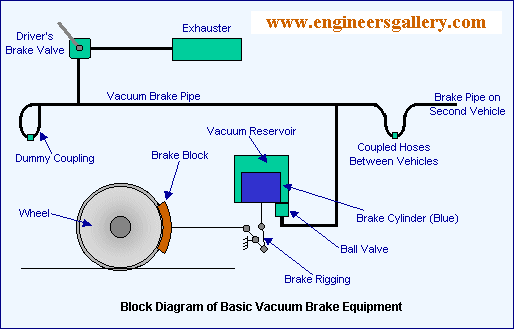
In its simplest form, the automatic vacuum brake consists of a continuous pipe—the train pipe—running throughout the length of the train. In normal running a partial vacuum is maintained in the train pipe, and the brakes are released. When air is admitted to the train pipe, the air pressure acts against pistons in cylinders in each vehicle. A vacuum is sustained on the other face of the pistons, so that a net force is applied. A mechanical linkage transmits this force to brake shoes which act on the treads of the wheels.

The fittings to achieve this are:
- a train pipe: a steel pipe running the length of each vehicle, with flexible vacuum hoses at each end of the vehicles, and coupled between adjacent vehicles; at the end of the train, the final hose is seated on an air-tight plug;
- an ejector on the locomotive, to create vacuum in the train pipe;
- controls for the driver to bring the ejector into action, and to admit air to the train pipe; these may be separate controls or a combined brake valve;
- a brake cylinder on each vehicle containing a piston, connected by rigging to the brake shoes on the vehicle; and
- a vacuum (pressure) gauge on the locomotive to indicate to the driver the degree of vacuum in the train pipe.
The brake cylinder is contained in a larger housing—this gives a reserve of vacuum as the piston operates. The cylinder rocks slightly in operation to maintain alignment with the brake rigging cranks, so it is supported in trunnion bearings, and the vacuum pipe connection to it is flexible. The piston in the brake cylinder has a flexible piston ring that allows air to pass from the upper part of the cylinder to the lower part if necessary.
When the vehicles have been at rest, so that the brake is not charged, the brake pistons will have dropped to their lower position in the absence of a pressure differential (as air will have leaked slowly into the upper part of the cylinder, destroying the vacuum).
When a locomotive is coupled to the vehicles, the driver moves the brake control to the “release” position and air is exhausted from the train pipe, creating a partial vacuum. Air in the upper part of the brake cylinders is also exhausted from the train pipe, through a non-return valve.
If the driver now moves his control to the “brake” position, air is admitted to the train pipe. According to the driver’s manipulation of the control, some or all of the vacuum will be destroyed in the process. The ball valve closes and there is a higher air pressure under the brake pistons than above it, and the pressure differential forces the piston upwards, applying the brakes. The driver can control the amount of braking effort by admitting more or less air to the train pipe.
Limitations
The progress represented by the automatic vacuum brake nonetheless carried some limitations; chief among these were:
- the practical limit on the degree of vacuum attainable means that a very large brake piston and cylinder are required to generate the force necessary on the brake blocks; when a proportion of the British ordinary wagon fleet was fitted with vacuum brakes in the 1950s, the physical dimensions of the brake cylinder prevented the wagons from operating in some private sidings that had tight clearances;
- for the same reason, on a very long train, a considerable volume of air has to be admitted to the train pipe to make a full brake application, and a considerable volume has to be exhausted to release the brake (if for example a signal at danger is suddenly lowered and the driver requires to resume speed); while the air is traveling along the train pipe, the brake pistons at the head of the train have responded to the brake application or release, but those at the tail will respond much later, leading to undesirable longitudinal forces in the train. In extreme cases this has led to breaking couplings and causing the train to divide.
- the existence of vacuum in the train pipe can cause debris to be sucked in. An accident took place near Ilford in the 1950s, due to inadequate braking effort in the train. A rolled newspaper was discovered in the train pipe, effectively isolating the rear part of the train from the driver’s control. The blockage should have been detected if a proper brake continuity test had been carried out before the train started its journey.
Stopping Trains by Atmospheric Pressure
THERE is a saying that “competition is healthy.” This in railway mechanics is decidedly so, as it makes for efficiency. One of the most outstanding examples is that of the rival braking systems, compressed air and vacuum.
Both are efficient and reliable ; each possesses advantages ; and before the general grouping of the railways, each had its adherents. The London, Brighton and South Coast, Great Eastern, North Eastern, London Chatham and Dover, and other lines used the Westinghouse air brakes, while the London and North Western, London and South Western, Great Northern, Midland, and others, pinned their faith to the vacuum automatic brake. Perhaps the best example of the rival brakes working side-by-side, as one might say, was that of the Underground in the old steam days, when the District locomotives and trains were provided with the Westinghouse apparatus and the Metropolitan had vacuum brakes. Both companies’ engines were identical, and often—as when running on the Inner Circle—worked exactly the same services over the same sets of metals. Even to the present day, the “rivals” go hand-in-hand ; on the Southern Railway, the electric trains use the quick-acting Westinghouse brake, and the steam trains are all vacuum-fitted. Each system gives perfectly satisfactory service.
The vacuum brake was invented while the compressed-air brake was in its infancy. It was hardly likely that any one system would be allowed to reign unchallenged ; and inventors who are always busy on the brake problem, hit on the idea of letting air at atmospheric pressure operate the pistons of their brake cylinders, by creating a vacuum in one end of the cylinder. Nature abhors a vacuum, and does her best to fill it with anything convenient. This can be demonstrated by a small glass syringe with a piston which is air-tight. Put a finger over the nozzle, and pull out the piston-rod as far as it will go ; this creates a vacuum in the syringe. Take away the finger, and air rushes in with a distinct hiss and “plop.” Repeat the experiment, but this time hold the nozzle under water before removing the finger, and water will rush into the syringe as soon as the nozzle is uncovered.

Again repeat the first experiment ; this time do not uncover the nozzle, but let go the piston-rod. It will fly back, because of the pressure of the atmosphere on the outside of the piston, and absence of pressure—hence no resistance—inside the syringe. Pull out the piston-rod once more ; attach a short length of rubber tube to the nozzle, and suck the air from the syringe. As one draws out the air and reduces the amount in the barrel of the syringe, the piston will move inwards, as the pressure of the atmosphere acts on the outer side of the piston ; and there one has the vacuum brake in the embryo.
The ejector is oneself, the rubber tube is the train pipe ; the syringe is the brake cylinder ; and if one attached the pull-rod of a miniature brake set to the piston-rod it would apply the brakes.
As with the compressed-air brake, the first vacuum brake was of the non-automatic. or “straight” type. Under the engine, and under each coach, was a brake cylinder which was not unlike a concertina, being collapsible. One end of the “concertina” was fixed, and the other end was attached to the brake pull-rods. All the “concertinas” were connected by a pipe running right through the train, connections between the carriages being made by flexible hoses with universal snap couplings, after the same style as the air brake.
Reference Wikipedia and mike’s railway history

